Bending machine for metal products and corresponding bending method

a technology of bending machine and metal products, applied in the field of bending machine and the corresponding bending method, can solve the problems of compromising the correct functioning, compromising the safety of the operator, and limiting the length of offcuts or their length

Active Publication Date: 2017-05-02
M E P MASCH ELECTRONICS PIEGATRICI SPA
View PDF7 Cites 0 Cited by
  • Summary
  • Abstract
  • Description
  • Claims
  • Application Information

AI Technical Summary

Benefits of technology

[0021]The presence of the secondary drawing or extraction unit allows to work a part of the bar that it is not possible to work with current solutions, thus limiting offcuts or their length, given that the secondary drawing or extraction unit is positioned immediately upstream of the main shearing unit.
[0022]The secondary drawing or extraction unit is also able to take the rear portion of each bar to a position such as to allow it to be discharged automatically, simply by the subsequent bar sent to the shearing and bending cycle: this gives advantages in terms of safety for the operator, who thus does not have to intervene manually to remove the offcuts.
[0025]According to a variant, the holding pipe has a conformation at least at the end which facilitates the introduction of the metal bar.

Problems solved by technology

The manual solution often entails stopping the machine, lifting the cover and removing the segment, with obvious loss of time and problems in terms of safety for the operator.
However, there is a risk that the discharged offcut may interfere with the bending unit or with other operating units that can be present on the bending machine, compromising the correct functioning thereof and obliging the operator to intervene in any case.
Furthermore, this solution does not guarantee sufficient safety for the operator, since the offcuts are discharged in an uncontrolled manner and can hit the operator.
Another disadvantage is the quantity and length of the offcuts.
In other words, the discard of material to be removed from the work cycle is a considerable cost.
These disadvantages can lead to losses in productivity, even considerable, for example where the segment gets jammed, or can lead to injuries to the operator, for example where the thickness is put in an anomalous and unsafe position.

Method used


Image

  • Bending machine for metal products and corresponding bending method
  • Bending machine for metal products and corresponding bending method
  • Bending machine for metal products and corresponding bending method

Examples


Embodiment Construction

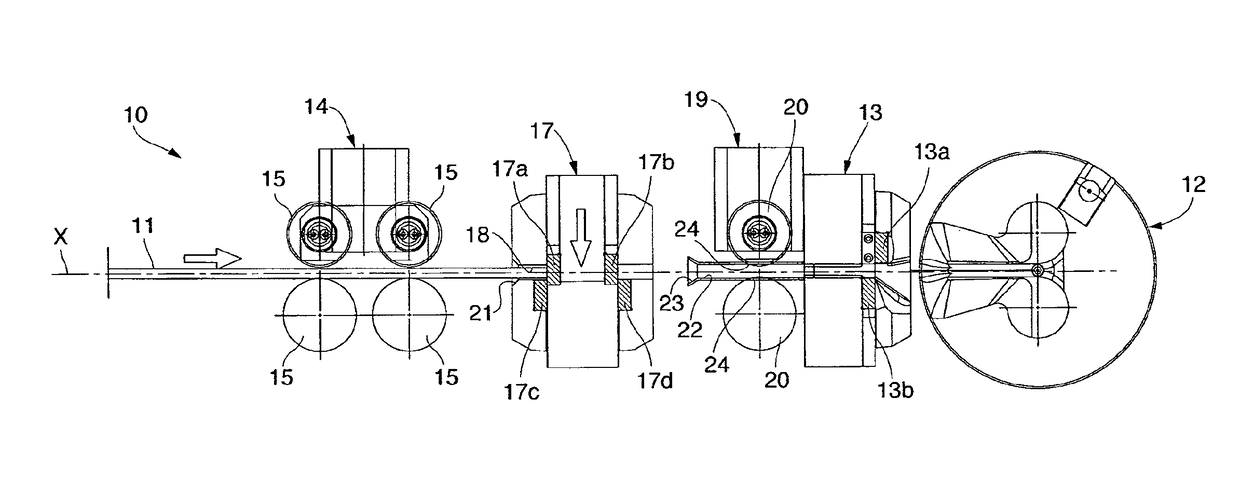
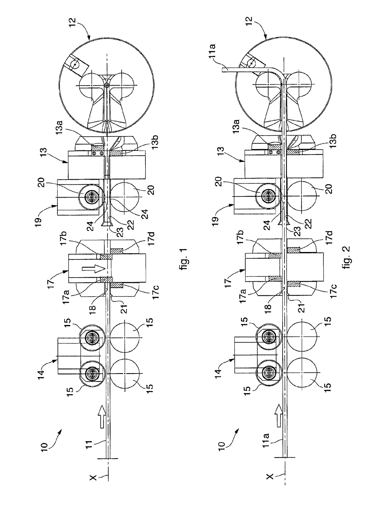
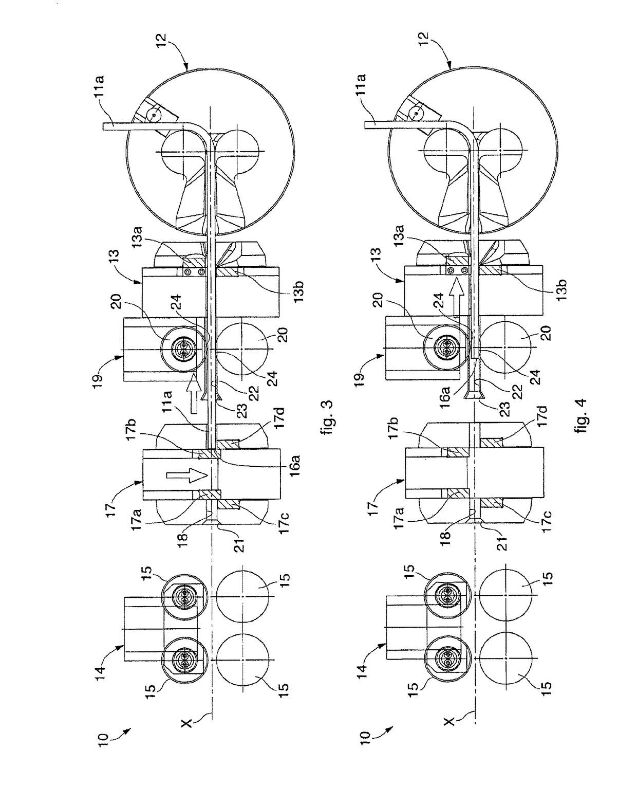
[0033]With reference to FIGS. 1-7, a bending machine 10, shown only partially, according to the present invention is used for bending metal products such as for example bars, reinforcement round pieces, structural shapes, tubes or other profiles with any section shape whatsoever.

[0034]Hereafter in the description, the word bar shall be understood to include both bars and reinforcement round pieces, structural shapes, tubes or other profiles with any section shape whatsoever.

[0035]The bending machine 10 is configured so as to selectively work one or more bars simultaneously.

[0036]Hereafter in the description, the bars will be identified generically by the reference number 11. Given that the bars 11 are inserted and worked in sequence, one after the other, a first bar introduced will be identified by the reference number 11a, while the bar introduced after 11a will be identified by the reference number 11b.

[0037]In this case, the bending machine 10 comprises a bending unit 12, in thi...


PUM

PropertyMeasurementUnit
thrustaaaaaaaaaa
shapeaaaaaaaaaa
sizeaaaaaaaaaa

Abstract

Bending machine for one or more metal products such as, for example, bars (11a, 11b), reinforcement round pieces, structural shapes, tubes or other profiles, comprising at least a bending unit, a main drawing unit, able to draw the bar along an axis of advance toward the bending unit, and a main shearing unit disposed between the bending unit and the main drawing unit. The machine also comprises a secondary drawing or extraction unit disposed between the main drawing unit and the main shearing unit. The secondary drawing or extraction unit is configured and programmed to draw an end portion of bar, exiting from the main drawing unit, along the axis of advance toward the bending unit.

Description

FIELD OF THE INVENTION[0001]The present invention concerns a bending machine and the corresponding bending method for metal products such as for example bars, reinforcement round pieces, structural shapes, tubes or other profiles with any section shape whatsoever.BACKGROUND OF THE INVENTION[0002]Bending machines for metal products such as, for example, bars, reinforcement round pieces, structural shapes, tubes or other profiles, with any section shape whatsoever are known, for shaping stirrups or other shaped reinforcement products. Examples of such bending machines are shown in documents WO 2007 / 141273 A1, WO 03 / 24640 A1 and WO 2012 / 143776 A1, all in the name of the present Applicant.[0003]These machines normally consist of a main drawing unit, for example with rollers, which feeds the bars toward a bending unit, and a shearing unit, for example shears, interposed between the main drawing unit and the bending unit, which shears the shaped bars to take them to the size corresponding...

Claims


Application Information

Patent Timeline
Patent Type & Authority Patents(United States)
IPC IPC(8): B21D7/02B21D7/022B21C1/00B21D11/12
CPCB21D7/022B21C1/00B21D11/12
Inventor DEL FABRO, GIORGIO
Owner M E P MASCH ELECTRONICS PIEGATRICI SPA
Why Eureka
Try Eureka