
Vending machine with elevator delivery of vended product to customer access

a vending machine and elevator technology, applied in the field of vending machines, can solve the problems of limited number of carousels, products not conducive to gravity delivery, and inability to drop vending devices for products, so as to improve the safety of other products, facilitate customer access to products, and ensure the effect of product quality

Active Publication Date: 2017-05-02
FAWN ENG
View PDF96 Cites 11 Cited by
  • Summary
  • Abstract
  • Description
  • Claims
  • Application Information

AI Technical Summary

Benefits of technology

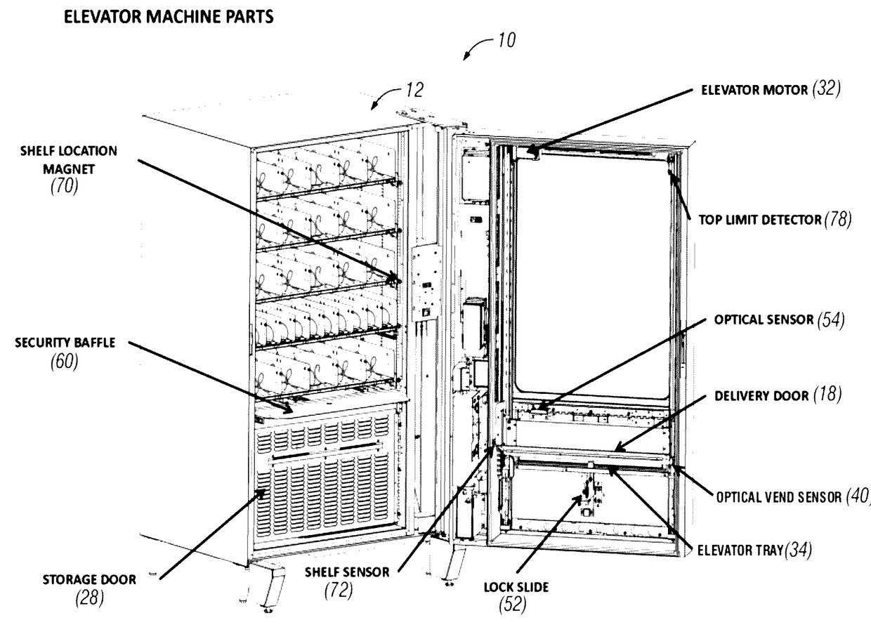
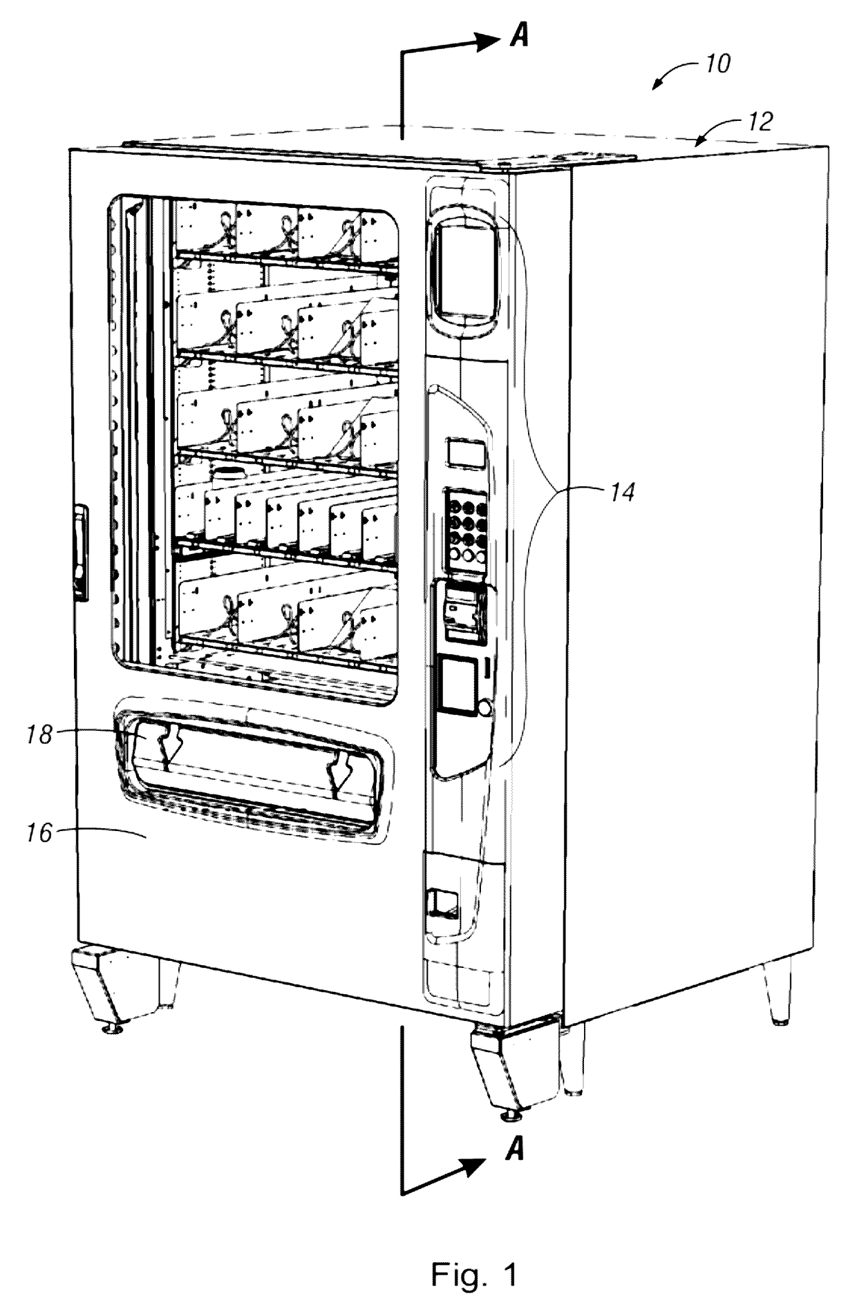
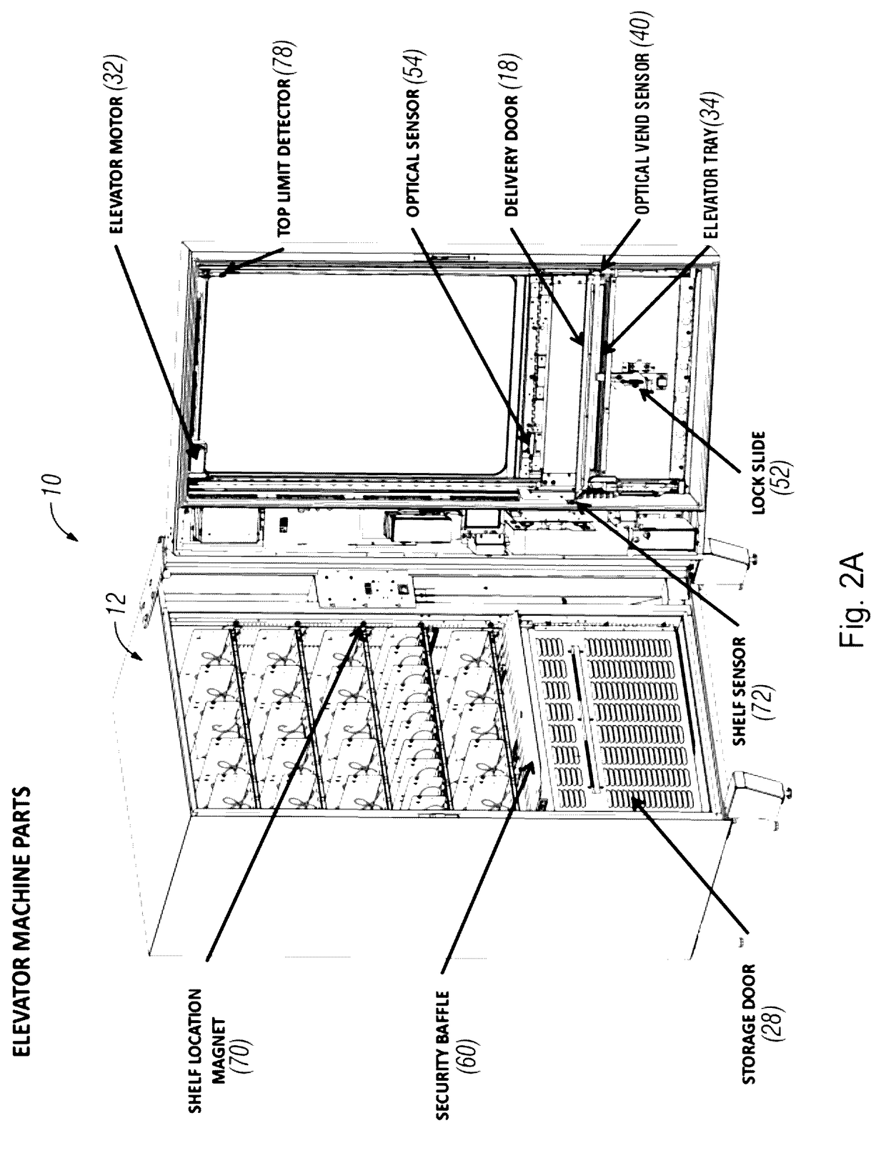
[0005]In one aspect of the present invention, an automated vending or merchandising machine includes an elevator sub-assembly which moves a dispensing bin or elevator tray vertically along the fronts of plural vertical levels of product dispensers in the vending machine. A controller tracks the vertical position of the elevator tray. This allows the controller to (a) send the elevator tray to the vertical level of the dispenser of the product selected by a customer, (b) at that level receive and confirm dispension of the selected product into the elevator tray, and (c) return the elevator tray holding the dispensed product down to a customer delivery or access door or opening in the vending machine that can below the vertical levels of dispensers. Features can include coordination of locking and unlocking of a customer access door and actuating an anti-cheat security baffle with the position of the elevator tray. The coordination can provide high assurance that the selected product is dispensed, there is convenient access to the product for the customer, and there is good security of the other products in the vending machine.
[0006]The present invention includes, as a general feature, the concept of a vending machine cabinet having at least one dispenser which moves a row of vendible product to a dispensing location. This includes machines having one or more dispensers on each of a plurality of horizontal shelves top to bottom. Each shelf can hold a plurality of individual back-to-front dispenser cartridges (in one example helix type dispensers) that a customer can select from. However, other dispenser types and methods are possible. In one possible aspect of the invention, a main difference from a conventional vending machine is a vertical elevator automatically moves a bin or tray (it can extend the width of all dispensers on a shelf) from a bottom “stand by” or “ready to vend” position up to just below the shelf of the selected dispenser. The dispenser slides the product into the bin instead of free-falling in a drop zone. Optionally, an optical sensing sub-system can sense if the product is actually moved from dispenser to bin. One example of the optical sensing sub-system has emitters on one side of the elevator just above the bin which direct infrared light in beams in a vertical plane across the vend space just below the front of the dispensers for that tray to detectors on the other lateral side of the bin. Thus, when the product slides out of a dispenser and drops by gravity vertically into the vend space and diagonally down into the elevator bin, it must pass through the beams in the vertical plane. This allows the machine to know a product moved generally horizontally from the dispenser and down into the bin. If the product is sensed, the elevator then automatically moves down to a “park” position which is near a customer-accessible delivery door.
[0010]1) An elevator to move a delivery tray for dispensed product between a lower position near a customer access door and raised positions at dispensers higher inside the machine. One advantage can be more gentle handling of vended items (they do not drop by gravity for 4 or 5 feet onto a steel bin floor). Optionally the elevator tray can have a specific configuration. In addition to machine-wide, it could have a sloped floor to promote ease of access to vended products by the customer and other features. It can also carry sensors or components to assist in operational features of the system.
[0016]4) A component (e.g. non-exclusive dual magnetic encoder driven by the elevator motor shaft) can also signal or inform the controller of elevator status and location. In one example, the controller can determine direction, position, and speed of the delivery bin. As the elevator tray passes each shelf, markers (such as described above) can be detected and the corresponding encoder count is mapped. This can be done automatically or require human intervention at each shelf level to verify and store the appropriate encoder count for each shelf location. This feature can assist in informing the controller of the vertical location and status of the delivery elevator tray or product tray.
[0022]9) Optionally, other sensors can inform the controller of state of the components. One example is a top limit detector which prevents overrun of elevator past the top shelf.

Problems solved by technology

The drop vend method may not be practical for products that can be damaged or deformed in the drop.
Nor may the gravity chute for similar reasons or that some products are not conducive to delivery by gravity.
The carousel method is limited in the number of items that can be stocked in the vending machine.
If a single carousel, it limits the choices.
Also, if multiple horizontal trays are stacked vertically in a carousel, it can be difficult for some persons to reach all trays.
Such an arrangement may also not meet Americans with Disabilities Act regulations which define an acceptable range of heights from the ground or floor for access to a vended product.

Method used


Image

  • Vending machine with elevator delivery of vended product to customer access
  • Vending machine with elevator delivery of vended product to customer access
  • Vending machine with elevator delivery of vended product to customer access

Examples


Embodiment Construction

[0045]A. Overview

[0046]For a better understanding of the invention, exemplary embodiments will be described below. The invention can take many forms and embodiments and this embodiment is but one way.

[0047]This embodiment will be discussed in the context of a vending or automated merchandising machine that includes an insulated cabinet and condenser / evaporator to maintain refrigerated or frozen food at appropriate temperatures, such as are well known in this technological field. The vending machine can also vend non-refrigerated foods or other products. This embodiment is also described in the context of plural helix-type dispensers, such as are well known in the technological field. It also has those dispensers arranged in multiple rows (shelves) and columns within the interior of the cabinet, with all dispensers dispensing inventory one-at-a-time forwardly towards a front, which comprises a main door to the cabinet with a glass window for customers to view the inventory. Examples ...


PUM


Abstract

An automated vending or merchandizing machine includes an elevator sub-assembly which moves a dispensing bin or elevator tray vertically along the fronts of plural vertical levels of product dispensers in the vending machine. A controller tracks the vertical position of the elevator tray. This allows the controller to send the elevator tray to the vertical level of the dispenser of the product selected by a customer, at that level receive and confirm dispensing of the selected product into the elevator tray, and return the elevator tray holding the dispensed product down to a customer delivery or access door or opening in the vending machine that can below the vertical levels of dispensers. Features can include coordination of locking and unlocking of a customer access door and actuating an anti-cheat security baffle with the position of the elevator tray.

Description

CROSS-REFERENCE TO RELATED APPLICATIONS[0001]This application claims priority under 35 U.S.C. §119 to provisional applications Ser. No. 61 / 460,538 filed Jan. 4, 2011, and Ser. No. 61 / 460,594, filed Jan. 5, 2011, each of which is herein incorporated by reference in its entirety.I. BACKGROUND[0002]A variety of dispensing and delivery methods are used in vending machines. For multiple product types, shapes, or sizes, two conventional methods are either: (a) individual horizontal dispensers which drop one product at a time to a dispensing bin for customer access or (b) a carousel which rotates the selected product in a multi-partitioned tray to a vending door for customer access. Others move a product to a chute which guides the product by gravity to a delivery opening.[0003]The drop vend method may not be practical for products that can be damaged or deformed in the drop. Nor may the gravity chute for similar reasons or that some products are not conducive to delivery by gravity. Examp...

Claims


Application Information

Patent Timeline
Patent Type & Authority Patents(United States)
IPC IPC(8): G06F17/00G07F9/02G07F11/04B65D83/00B65G59/00G07F11/16G07F11/36
CPCG07F11/04G07F9/02G07F11/165G07F11/36G07F9/009
Inventor PRITCHARD, GRANTMAYOROS, JEFFREY W.LAD, SANTOSH
Owner FAWN ENG
Learn More