Porous ceramic material, manufacturing method and use thereof

a manufacturing method and ceramic material technology, applied in the field of porous ceramic material manufacturing, can solve the problems of poor mechanical properties, poor uniformity of pore distribution, low production efficiency, shape and density of the product obtained, etc., and achieve controllable pore size, good mechanical properties, and high porosity

Active Publication Date: 2017-05-16
SHENZHEN SMOORE TECH LTD +2
View PDF2 Cites 43 Cited by
  • Summary
  • Abstract
  • Description
  • Claims
  • Application Information

AI Technical Summary

Benefits of technology

[0005]Accordingly, it is necessary to provide a manufacturing method of a porous ceramic material with high porosity, controllable pore size, and better mechanical properties and the porous ceramic material.
[0006]It is also necessary to provide a porous ceramic material with high porosity, controllable pore size, and better mechanical properties.
[0007]It is also necessary to provide an atomizer for an electronic cigarette with high production efficiency and long life time.
[0014]In the aforementioned manufacturing method of the porous ceramic material, the space-holder method is combined with the injection molding method, such that the obtained porous ceramic material has a high porosity, controllable pore sizes and good mechanical properties. In addition, compared with the dry pressing process, the use of the injection molding process can significantly improve the production efficiency, and is suitable for large-scale production.

Problems solved by technology

However, these aforementioned methods all have their own limitations, for example, the porous ceramic material prepared according to space-holder method has a poor pore distribution uniformity and poor mechanical properties, as well as low production efficiency; the shape and the density of the product obtained by polymeric sponge dipping method is difficult to control; the foaming method requires a higher demand for raw materials, and the process conditions is difficult to control; the porosity of the product obtained by particle packing method is low.
Therefore, it is an urgent problem how to manufacture a porous ceramic material with high porosity, controllable pore size, and good mechanical properties.
However, the current common atomizer for the electronic cigarette composed by multiple components has the disadvantages of complicated structure, complex production process and short life time.

Method used


Image

  • Porous ceramic material, manufacturing method and use thereof
  • Porous ceramic material, manufacturing method and use thereof
  • Porous ceramic material, manufacturing method and use thereof

Examples


example 1

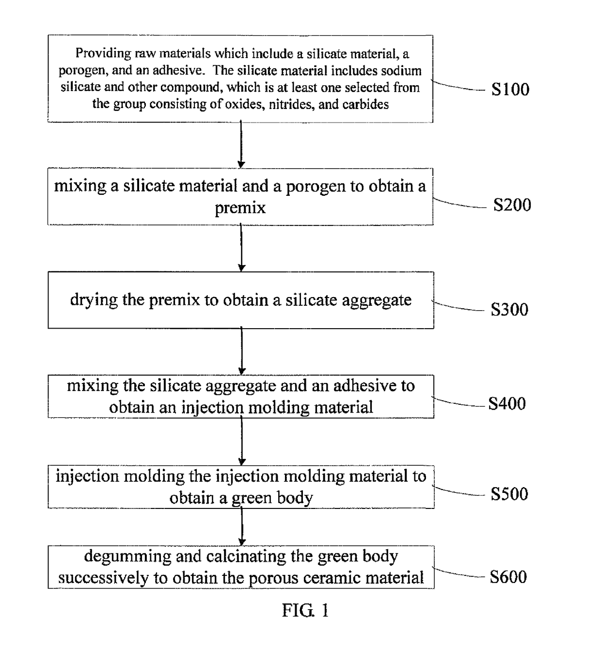
[0081]After the alumina powder was ground and passed through a 80 mesh screen, 400 g of alumina powder was weighed, 60 g of sawdust which passed through 80 to 100 mesh screen was added, the mixture was mixed in a ball mill for 30 min, 230 g of industrial sodium silicate with a modulus of 2.6 was added, stirred and mixed for 30 min to obtain a premix.

[0082]The premix was placed in oven and dried at 80° C. for 400 min, so as to obtain dry silicate aggregate.

[0083]The mixer was preheated to 220° C., 20 g of polypropylene was then added to the mixer. After the polypropylene was melt completely, it was cooled to 170° C., 400 g of silicate aggregate, 300 g of paraffin wax were then added, mixed for 1 h; 40 g of stearic acid, 40 g of dibutyl phthalate were continuously added, mixed for 2 h, thus obtaining the injection molding material.

[0084]The injection molding material was cooled, diced by jaw crusher equipment. The diced injection molding material was fed to the hopper of an injection ...

example 2

[0087]After the zirconia powder was ground and passed through a 60 mesh screen, 400 g of zirconia powder was weighed, 80 g of sawdust which passed through 80 to 100 mesh screen was added, the mixture was mixed in a ball mill for 40 min, 160 g of industrial sodium silicate with a modulus of 2.8 was added, stirred and mixed for 20 min to obtain a premix.

[0088]The premix was placed in oven and dried at 100° C. for 300 min, so as to obtain dry silicate aggregate.

[0089]The mixer was preheated to 220° C., 40 g of polypropylene was then added to the mixer. After the polypropylene was melt completely, it was cooled to 170° C., 400 g of silicate aggregate, 280 g of paraffin wax were then added, mixed for 1 h; 40 g of stearic acid, 40 g of dibutyl phthalate were continuously added, mixed for 2 h, thus obtaining the injection molding material.

[0090]The injection molding material was cooled, diced by jaw crusher equipment. The diced injection molding material was fed to the hopper of an injecti...

example 3

[0092]After the silicon nitride powder was ground and passed through a 100 mesh screen, 400 g of silicon nitride powder was weighed, 133 g of graphite which passed through 200 mesh screen was added, the mixture was mixed in a ball mill for 30 min, 355 g of industrial sodium silicate with a modulus of 1.5 was added, stirred and mixed for 30 min to obtain a premix.

[0093]The premix was placed in oven and dried at 110° C. for 300 min, so as to obtain dry silicate aggregate.

[0094]The mixer was preheated to 220° C., 20 g of polypropylene was then added to the mixer. After the polypropylene was melt completely, it was cooled to 170° C., 400 g of silicate aggregate, 320 g of paraffin wax were then added, mixed for 1 h; 40 g of stearic acid, 40 g of dibutyl phthalate were continuously added, mixed for 2 h, thus obtaining the injection molding material.

[0095]The injection molding material was cooled, diced by jaw crusher equipment. The diced injection molding material was fed to the hopper of...


PUM

PropertyMeasurementUnit
temperatureaaaaaaaaaa

Abstract

The present invention relates to a manufacturing method of a porous ceramic material, which includes the following steps: mixing a silicate material and a porogen to obtain a premix, wherein the silicate material includes sodium silicate and other compounds being at least one selected from the group consisting of oxides, nitrides, and carbides; drying the premix to obtain a silicate aggregate; mixing the silicate aggregate and an adhesive to obtain an injection molding material, wherein in a weight percentage, the silicate aggregate is in the range of from 50% to 60%, the adhesive is in the range of from 40% to 50%; injection molding the injection molding material to obtain a green body; and degumming and calcinating the green body successively to obtain the porous ceramic material. In the aforementioned manufacturing method of the porous ceramic material, the space-holder method is combined with the injection molding method, such that the obtained porous ceramic material has a high porosity, controllable pore sizes and good mechanical properties. In addition, compared with the dry pressing process, the use of the injection molding process can significantly improve the production efficiency, and is suitable for large-scale production.

Description

FIELD OF THE INVENTION[0001]The present disclosure relates to ceramic material manufacturing, and more particularly relates to a manufacturing method of a porous ceramic material, porous ceramic material and use thereof.BACKGROUND OF THE INVENTION[0002]Ceramic material is a kind of inorganic non-metallic material obtained by molding and high temperature sintering natural or synthetic compounds, which has very wide applications.[0003]The current common industrial porous ceramic material is manufactured by space-holder method, polymeric sponge dipping method, foaming method, injection molding method, particle packing method, etc. However, these aforementioned methods all have their own limitations, for example, the porous ceramic material prepared according to space-holder method has a poor pore distribution uniformity and poor mechanical properties, as well as low production efficiency; the shape and the density of the product obtained by polymeric sponge dipping method is difficult ...

Claims


Application Information

Patent Timeline
Patent Type & Authority Patents(United States)
IPC IPC(8): C04B38/00B28B11/24A24F47/00B05B17/00B28B1/24C03C11/00A24F40/10A24F40/44A24F40/70
CPCA24F47/008B05B17/00B28B1/24B28B11/243C03C11/00A24F40/44A24F40/10A24F40/70
Inventor ZHOU, HONGMINGXIA, QINGLUXIAO, KAIWENLI, JIANLIU, PINGKUN
Owner SHENZHEN SMOORE TECH LTD
Why Eureka
Try Eureka