Liquid crystal pixel circuit of liquid crystal display panel and driving method thereof

a technology of liquid crystal display panel and liquid crystal pixel circuit, which is applied in the direction of static indicating devices, instruments, cathode-ray tube indicators, etc., can solve the problem of high operating voltage and achieve the effect of improving the operating voltage range of liquid crystal

Active Publication Date: 2017-05-16
AU OPTRONICS CORP
View PDF9 Cites 1 Cited by
  • Summary
  • Abstract
  • Description
  • Claims
  • Application Information

AI Technical Summary

Benefits of technology

[0007]The invention provides a liquid crystal pixel circuit and a driving method thereof for improving an operating voltage range of liquid crystal in the liquid crystal pixel circuit.
[0015]Based on the above, the liquid crystal pixel circuit and the driving method thereof provided by the embodiments of the invention improve the operating voltage range of the liquid crystal in the liquid crystal pixel circuit by the DC voltage set externally and the capacitive coupling effect.

Problems solved by technology

However, for blue phase liquid crystal, the data voltage of the general liquid crystal pixel circuit is relatively low, which may cause the blue phase liquid crystal to have insufficient transmittance, and as a result, a higher operating voltage is required for use of blue phase liquid crystal.

Method used


Image

  • Liquid crystal pixel circuit of liquid crystal display panel and driving method thereof
  • Liquid crystal pixel circuit of liquid crystal display panel and driving method thereof
  • Liquid crystal pixel circuit of liquid crystal display panel and driving method thereof

Examples


Embodiment Construction

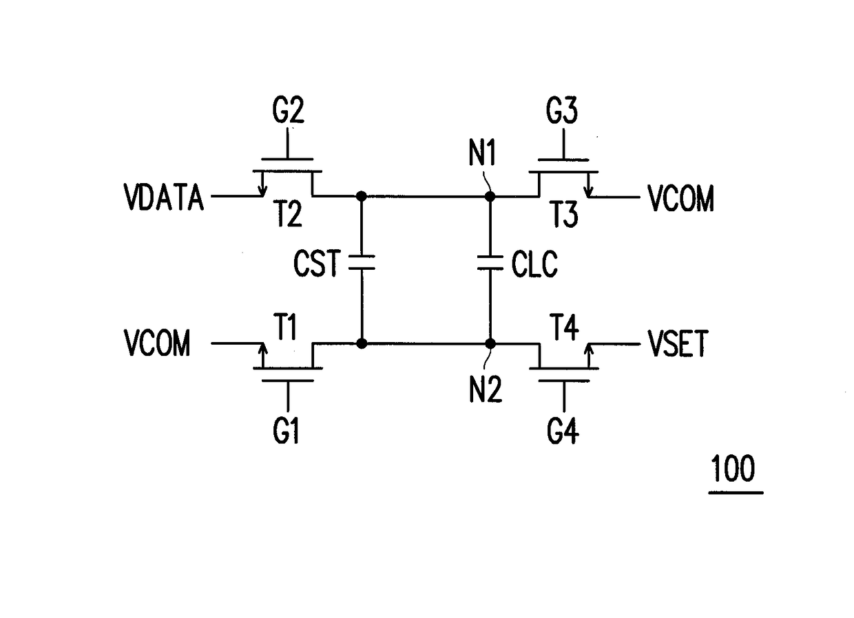
[0021]FIG. 1 is a circuit diagram of a pixel circuit 100 adapted for a liquid crystal display panel according to an embodiment of the invention. With reference to FIG. 1, in this embodiment, the pixel circuit 100 includes a first switch T1, a second switch T2, a storage capacitor CST, a liquid crystal capacitor CLC, a third switch T3, and a fourth switch T4. A first terminal of the first switch T1 receives a common voltage VCOM and a control terminal of the first switch T1 receives a first gate signal G1. A first terminal of the second switch T2 receives a data voltage VDATA and a control terminal of the second switch T2 receives a second gate signal G2. The storage capacitor CST and the liquid crystal capacitor CLC are coupled in parallel and are electrically coupled between a second terminal of the first switch T1 and a second terminal of the second switch T2. That is, a second terminal N2 of the liquid crystal capacitor CLC is electrically coupled with the second terminal of the ...


PUM


Abstract

A liquid crystal (LC) pixel circuit of a LC display panel includes a first, a second, a third and a fourth switches, a LC capacitor and a storage capacitor. A first and a control terminals of the first switch respectively receive a common voltage and a first gate signal. A first and a control terminals of the second switch respectively receive a data voltage and a second gate signal. The storage capacitor and the LC capacitor electrically connect between second terminals of the first and second switches. A first and a control terminals of the third switch respectively receive the common voltage and a third gate signal. A first and a control terminals of the fourth switch respectively receive a set voltage and a fourth gate signal. Second terminals of the third and the fourth switches respectively connect to the second terminals of the second and the first switches.

Description

CROSS-REFERENCE TO RELATED APPLICATION[0001]This application claims the priority benefit of Taiwan application serial no. 103111793, filed on Mar. 28, 2014. The entirety of the above-mentioned patent application is hereby incorporated by reference herein and made a part of this specification.BACKGROUND OF THE INVENTION[0002]Field of the Invention[0003]The invention relates to a liquid crystal pixel circuit and a driving method thereof, and more particularly relates to a liquid crystal pixel circuit capable of increasing an operating voltage range and a driving method thereof.[0004]Description of Related Art[0005]With the vigorous development of display technology, the standard that the users hold for display image quality gets higher and higher. Responsive to the users' demands with respect to the response time of a display, there are more and more manufacturers in the field of displays investing in the development of blue phase liquid crystal (BPLC) displays.[0006]Blue phase liquid...

Claims


Application Information

Patent Timeline
Patent Type & Authority Patents(United States)
IPC IPC(8): G09G5/00G09G3/36G09G5/10
CPCG09G3/3648G09G2310/06G09G2320/0252
Inventor LIN, CHIH-LUNGWU, CHIA-ENCHENG, MAO-HSUNTZENG, BO-SHIANGLIN, CHING-HUAN
Owner AU OPTRONICS CORP
Why Eureka
Try Eureka