Constant current circuit and light emitting diode driving device using the same

a technology of constant current and driving device, which is applied in the direction of constant-current supply dc circuit, process and machine control, instruments, etc., can solve the problems of systematic error in output current iout, output current may change, and light emitting diodes may change luminance, etc., to achieve high-accuracy constant current, increase the voltage range, and reduce the effect of chip area

Inactive Publication Date: 2013-04-11
RICOH ELECTRONIC DEVICES CO LTD
View PDF5 Cites 9 Cited by
  • Summary
  • Abstract
  • Description
  • Claims
  • Application Information

AI Technical Summary

Benefits of technology

[0043]According to an embodiment of the present invention, by having the detection circuit section that determines whether at least one of the first transistor and the second transistor is unable to output a current proportional to the first constant current while at least one of the first transistor and the second transistor operates in the linear region, it may become possible to substantially expand the voltage range at the output terminal where highly-accurate output current can be output, greatly improve the efficiency, and obtain far greater versatility.
[0044]Further, it may become possible to greatly reduce the chip area and output a highly-accurate constant current without depending on the terminal voltage which is the voltage of the connecting section to the load. Further, it may become possible to reduce the terminal voltage without degrading the constant current output accuracy and greatly reduce the power consumption.

Problems solved by technology

However, in this case, there is a problem that when the voltage at the output terminal greatly changes, due to the channel length modulation effect of the MOS transistor, the output current may change and as a result, the luminance of the light emitting diode may change.
As a result, a systematic error may be generated in the output current iout.
Therefore, there is a problem that a variable range of the voltage Vo at the output terminal OUT may be largely limited.

Method used


Image

  • Constant current circuit and light emitting diode driving device using the same
  • Constant current circuit and light emitting diode driving device using the same
  • Constant current circuit and light emitting diode driving device using the same

Examples


first embodiment

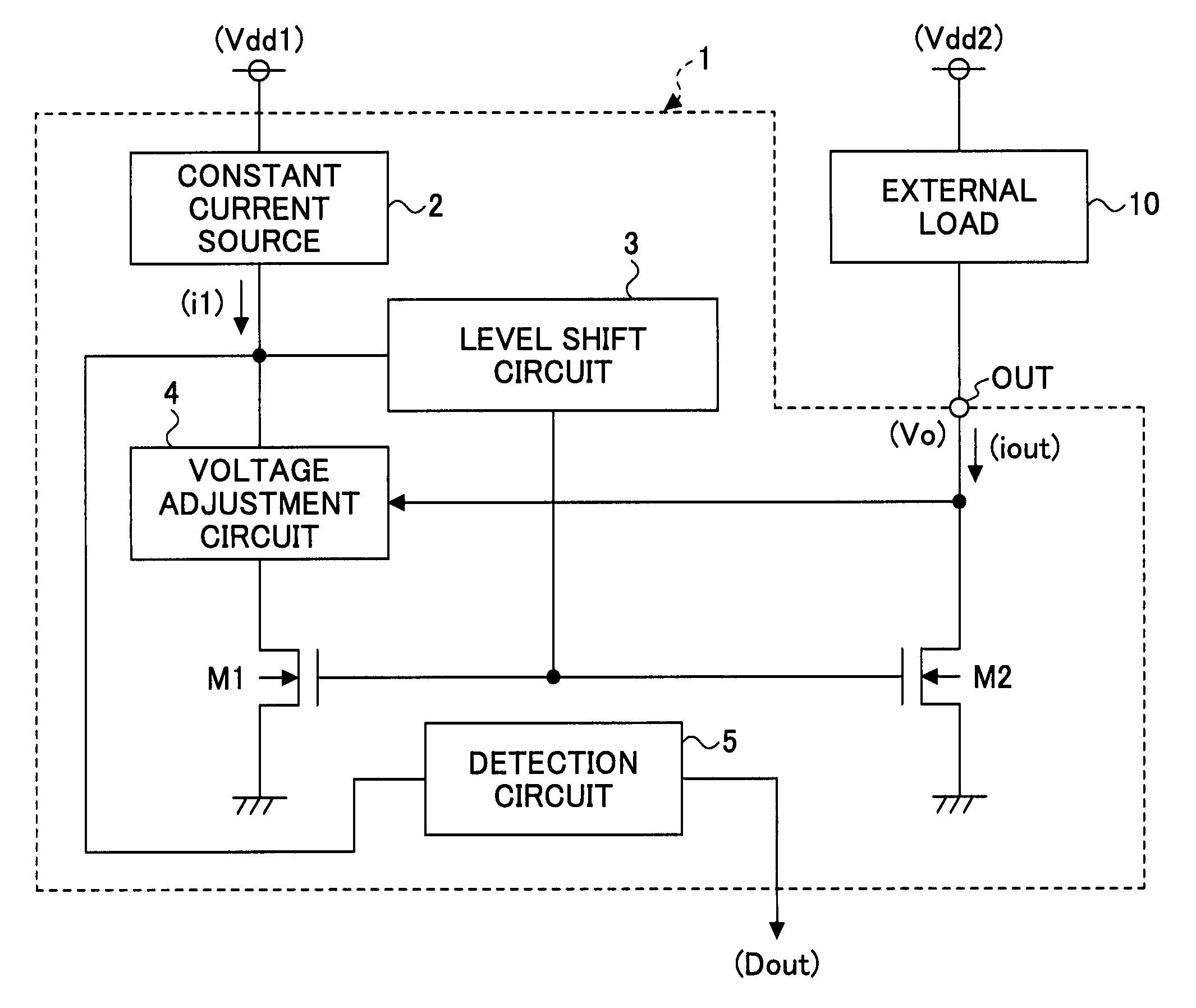
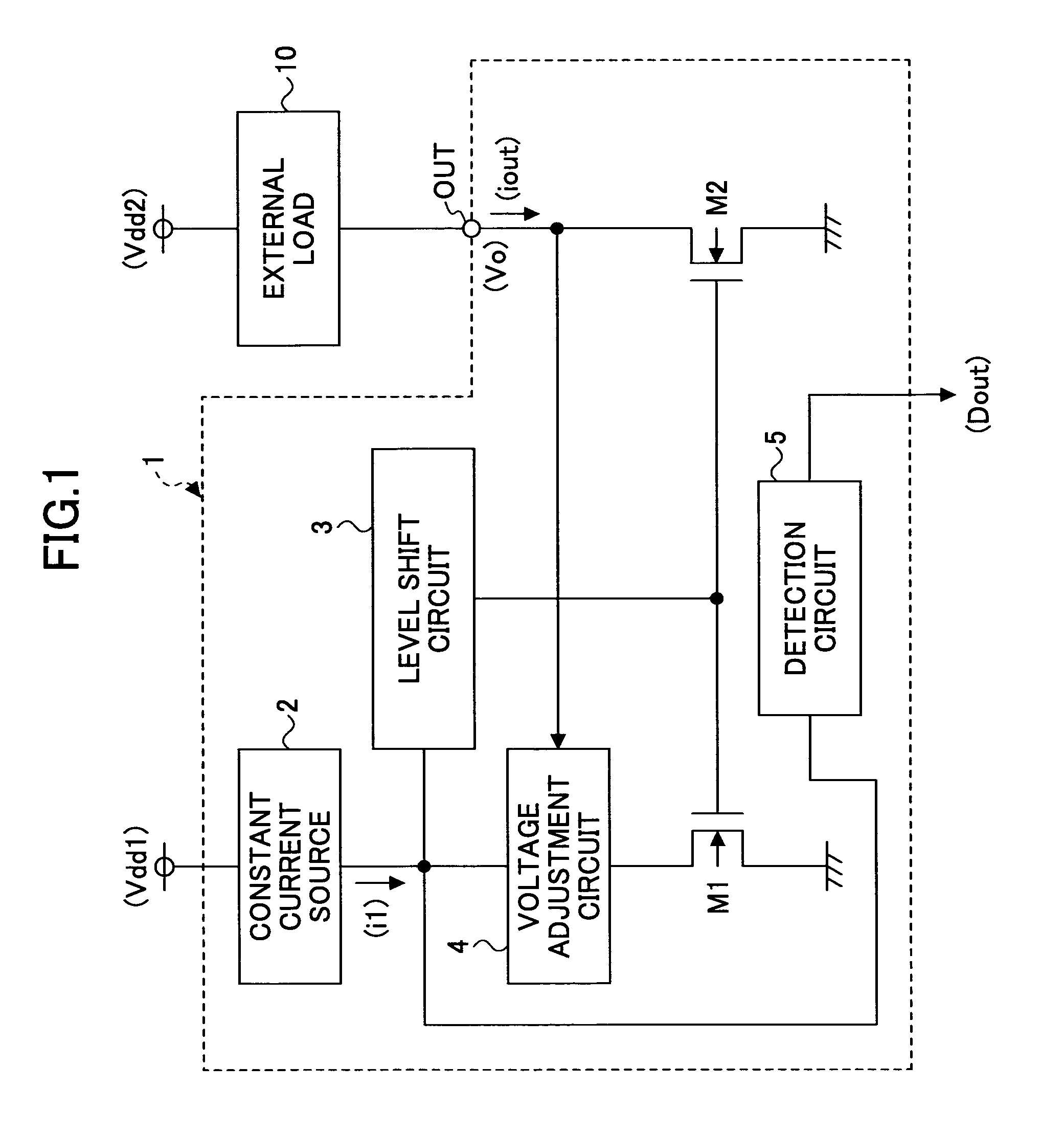
[0068]FIG. 1 is a block diagram illustrating an exemplary configuration of a constant current circuit according to a first embodiment of the present invention.

[0069]A constant current circuit 1 of FIG. 1 generates a predetermined constant current and supplies the constant current to an external load 10 such as a light emitting diode via the output terminal OUT. Further, the constant current circuit 1 includes NMOS transistors M1 and M2, a constant current source 2 generating and outputting a predetermined constant current, a level shift circuit 3, a voltage adjustment circuit 4, and a detection circuit 5. In FIG. 1, the external load 10 is a light emitting diode. When the constant current circuit 1 constitutes a light emitting diode driving device, the anode and the cathode of the light emitting diode are connected to a power-supply voltage Vdd2 and an output terminal OUT, respectively.

[0070]The external load 10 is connected between the power-supply voltage Vdd2 and the output termi...


PUM


Abstract

A constant current circuit includes a first transistor, a second transistor having the gate and the source connected to the gate and the source of the first transistor, and having the drain connected to a load, a voltage adjustment circuit section that controls the drain voltage of the first transistor, a constant current generation circuit section that supplies a constant current to the first transistor, and a detection circuit section that determines whether at least one of the first transistor and the second transistor is unable to output a current proportional to the first constant current while at least one of the first transistor and the second transistor operates in the linear region, by performing a voltage comparison between a voltage at a connecting section between the voltage adjustment circuit section and the constant current generation circuit section and a predetermined reference voltage.

Description

TECHNICAL FIELD[0001]The present invention relates to a constant current circuit, and more particularly to a constant current circuit for driving, for example, a light emitting diode (LED) and a light emitting diode driving device using the constant current circuit.BACKGROUND ART[0002]Generally, light emitting diodes (LEDs) for display devices are driven using a constant current to reduce the dispersion of the luminance of the LEDs. When the luminance is adjusted in accordance with the application of the light emitting diode, the current setting of the constant current circuit is changed. However, the voltage drop of the light emitting diode varies depending on the driving current. Because of this feature, the voltage at the output terminal (i.e., the voltage at the output terminal of the constant current circuit) may greatly vary.[0003]Generally, in the constant current circuit, the drain electrode of a MOS transistor is used as the output terminal. However, in this case, there is ...

Claims


Application Information

Patent Timeline
Patent Type & Authority Applications(United States)
IPC IPC(8): G05F3/24H05B37/02
CPCH05B37/02G05F3/24H05B47/10
Inventor NODA, IPPEI
Owner RICOH ELECTRONIC DEVICES CO LTD
Why Eureka
Try Eureka