Supercharge Your Innovation With Domain-Expert AI Agents!

Electrical switching apparatus and slot motor therefor

Active Publication Date: 2017-05-16
EATON INTELLIGENT POWER LIMITED
View PDF20 Cites 3 Cited by
  • Summary
  • Abstract
  • Description
  • Claims
  • Application Information

AI Technical Summary

Benefits of technology

The disclosed concept is about an electrical switching apparatus and a slot motor for it. The slot motor has a support element, multiple permanent magnets, and U-shaped plates. The support element has two legs, and each permanent magnet is located on one of the legs. The U-shaped plates are coupled to the support element. The technical effect of this invention is that it provides an improved design for the slot motor that increases the stability and efficiency of the electrical switching apparatus.

Problems solved by technology

The arc provides a means for smoothly transitioning from a closed circuit to an open circuit, but produces a number of challenges to the circuit breaker designer.
Among them is the fact that the arc results in the undesirable flow of electrical current through the circuit breaker to the load.
Additionally, the arc, which extends between the contacts, often results in vaporization or sublimation of the contact material itself.
A challenge with interruption is that there is often not enough current-induced magnetic force and gas dynamics to force the arc into the arc chute.
However, among other disadvantages, large permanent magnets are costly and significantly increase the size of the arc chute.

Method used


Image

  • Electrical switching apparatus and slot motor therefor
  • Electrical switching apparatus and slot motor therefor
  • Electrical switching apparatus and slot motor therefor

Examples


example 1

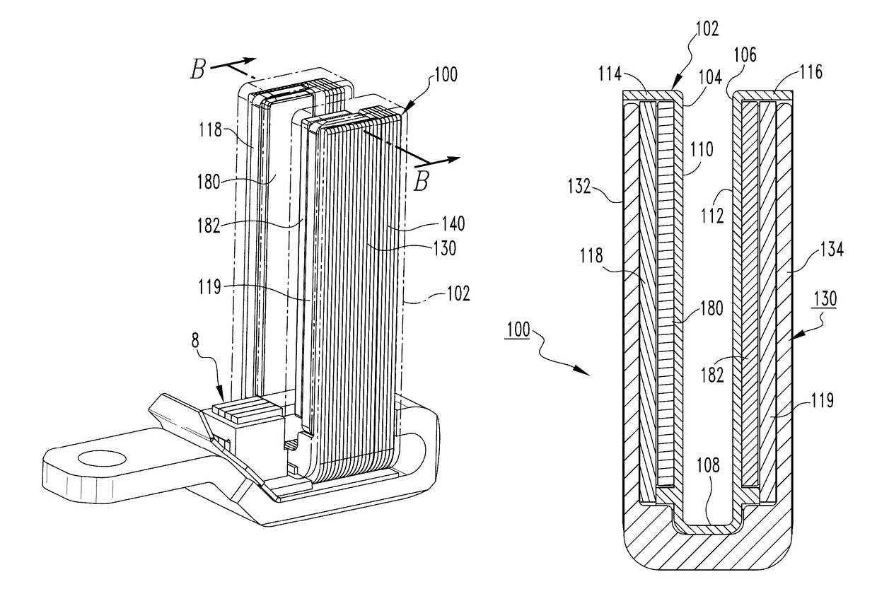
[0036]Each of the permanent magnets 180,182 may extend from proximate the middle portion 108 to proximate a respective distal end portion 114,116 of a respective one of the legs 104,106. Additionally, the permanent magnets 180,182 may have the same magnetic orientation, for example, with a south pole located proximate the lamination 140 and a north pole located opposite the south pole (i.e., between the south pole and the arc chute 10).

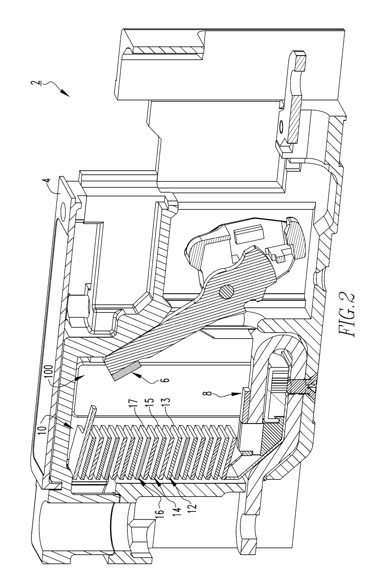
[0037]A computer generated illustration of the magnetic flux field generated by the slot motor 100 for a given direction of current interruption is shown in FIG. 7. As shown, the magnetic field is operable to exert a force toward the permanent magnet 182. More specifically, the permanent magnets 180,182 are cooperatively structured to magnetically attract an arc (i.e., an arc generated by the parting of the separable contacts 6,8 (FIG. 2)) into the second inner surface 112. It will be appreciated that in an opposite direction of current interruption, ...

example 2

[0042]The example of FIGS. 8 and 9 shows the alternative slot motor 200, which may be substituted into the circuit breaker 2 in place of any of the slot motors 100. As shown, the slot motor 200 includes a third permanent magnet 284 and a fourth permanent magnet 286, in addition to the first permanent magnet 280 and the second permanent magnet 282. Each respective leg 204,206 has a respective midpoint 205,207. The first permanent magnet 280 and the second permanent magnet 282 are located between the respective midpoints 205,207 and the middle portion 208. The third permanent magnet 284 and the fourth permanent magnet 286 are located between the respective midpoints 205,207 and the respective distal end portions 214,216.

[0043]Continuing to refer to FIGS. 8 and 9, the support apparatus further includes a third spacer 221 and a fourth spacer 223 in addition to the first and second spacers 218,219. As shown, the third spacer 221 is located between the first permanent magnet 280 and the t...

example 3

[0045]The example of FIG. 10 shows the alternative slot motor 300, which may be substituted into the circuit breaker 2 in place of any of the slot motors 100. As shown, there are only two relatively small permanent magnets 380,382 in the slot motor 300 (i.e., located between respective midpoints and the middle portion of the support element), advantageously resulting in a reduction in manufacturing costs.

[0046]It will also be appreciated that in this example there is a reversed magnetic field. More specifically, the permanent magnets 380,382 impart a magnetic force on the electrical arc toward a respective inner surface of the support element at the bottom of the support element, and the magnetic field is reversed at the top of the support element such that at the top of the support element, the electrical arc will be driven toward the opposing inner surface.

[0047]Although the examples disclosed herein have been described in association with the permanent magnets 180,182,280,282,284...


PUM


Abstract

A slot motor is for an electrical switching apparatus. The slot motor includes: a support apparatus including a support element having a first leg and a second leg located opposite the first leg, the first leg having a first inner surface, the second leg having a second inner surface facing the first inner surface; a plurality of permanent magnets including a first permanent magnet and a second permanent magnet, the first permanent magnet being located on the first leg, the second permanent magnet being located on the second leg; and a number of U-shaped plates coupled to the support element. The first inner surface and the second inner surface are located between the first permanent magnet and the second permanent magnet.

Description

BACKGROUND[0001]Field[0002]The disclosed concept relates to electrical switching apparatus, such as, for example, circuit breakers and, more particularly, to circuit breakers employing a slot motor. The disclosed concept further relates to slot motors.[0003]Background Information[0004]Electrical switching apparatus, such as circuit breakers, are employed in diverse capacities in power distribution systems. A circuit breaker may include, for example, a line conductor, a load conductor, a fixed contact and a movable contact, with the movable contact being movable into and out of electrically conductive engagement with the fixed contact. This switches the circuit breaker between an ON or closed position and an OFF or open position, or between the ON or closed position and a tripped or tripped OFF position. The fixed contact is electrically conductively engaged with one of the line and load conductors, and the movable contact is electrically conductively engaged with the other of the li...

Claims


Application Information

Patent Timeline
IPC IPC(8): H01H33/18
CPCH01H33/182H01H9/443H01H77/108H01H2003/268H01H2009/365H01H9/346H01H9/302H01H33/596
Inventor ZHOU, XINJUDS, MARK ALANRUEMPLER, CHRISTIANROLLMANN, PAUL JASONCARRODUS, JASON
Owner EATON INTELLIGENT POWER LIMITED
Features
  • R&D
  • Intellectual Property
  • Life Sciences
  • Materials
  • Tech Scout
  • Unparalleled Data Quality
  • Higher Quality Content
  • 60% Fewer Hallucinations
Learn More