System and method for ensuring minimal control delay to grouped illumination devices configured within a wireless network

a wireless network and control delay technology, applied in the field of illumination devices, can solve problems such as inability to assign scenes to groups

Active Publication Date: 2017-05-16
LUTRON TECH CO LLC
View PDF18 Cites 48 Cited by
  • Summary
  • Abstract
  • Description
  • Claims
  • Application Information

AI Technical Summary

Benefits of technology

[0015]According to yet another embodiment, the lighting controller device that controls the plurality of lamps not only provides a GUI to select groups of physical lamps and assign those groups to specific scenes based on their function and location within a residence, but also during the procedure of grouping and assigning a scene on the GUI (or content to the physical lamps) a visual indicator on the lamp icon and the named group icon is designed to correspond with a visual indicator from the physical lamp and physical keypad control device. By visually indicating on the physical devices (physical lamps and keypads within the residence) and virtual devices (lamp icons and keypad icons) on the GUI, commissioning of lamps and keypads during a discovery procedure and thereafter during a grouping procedure can be visually confirmed by the user. By indicating both in the physical realm as well as the virtual realm, the user is assured that all of the physical devices have been discovered by the controller and, thereafter, grouped properly by the controller.
[0018]A further advantage of the present groupcast control mechanism is that a novel aggregated acknowledgement message mechanism is employed. For each of the group of physical lamps which receive the groupcast, those lamps must return an acknowledge. In a mesh network, such as the present network, the acknowledge, if used, is sent across different lamp-to-lamp paths back to the control device so that the control device knows that each of the group of lamps received the command message. Unfortunately, sending an acknowledge back on multiple, different paths can be time consumptive and can also add to the delay if, for example, one of the group of lamps does not turn on when instructed by the command message. Having to send back multiple paths of acknowledge, with one lamp not turning on, causes another message command to be sent by the control device to the lamp that did not acknowledge. The present acknowledgement mechanism avoids this problem by forming routing tables through use of previous acknowledged paths, and maintaining those routing tables to ensure that an acknowledge from each of the group of physical lamps is sent over the same path instructed by the previous routing table acknowledgements and if by chance one lamp, or a select few do not acknowledge over that single path, they would acknowledge on possibly no more than one or two different paths without requiring the control device to send another control message. The aggregated acknowledge mechanism over a single path is not only beneficial from a time delay perspective, but also can be dynamically altered through use of the pre-existing routing tables if a relatively few number of lamps do not acknowledge, which typically is the case in most settings since physical lamps generally stay put in the home. Thus, although the acknowledge message is unicast as a single message with aggregated unique addresses at the grouped subset of physical lamps that receive the groupcast control message, the aggregated unique addresses of the group addresses subset is assured of being sent primarily as a single message and not as multiple messages across multiple unicast path which would unduly hamper the bandwidth of the control and acknowledge back mechanism.

Problems solved by technology

Such network lighting control systems recognize that it is unfeasible to assign scenes to a group of lamps interconnected through a network since it is burdensome for a user to do so and because there is an almost infinite number of possible lighting scenes.

Method used


Image

  • System and method for ensuring minimal control delay to grouped illumination devices configured within a wireless network
  • System and method for ensuring minimal control delay to grouped illumination devices configured within a wireless network
  • System and method for ensuring minimal control delay to grouped illumination devices configured within a wireless network

Examples


Embodiment Construction

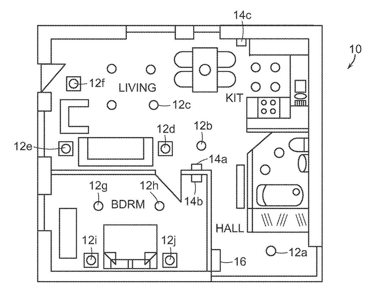
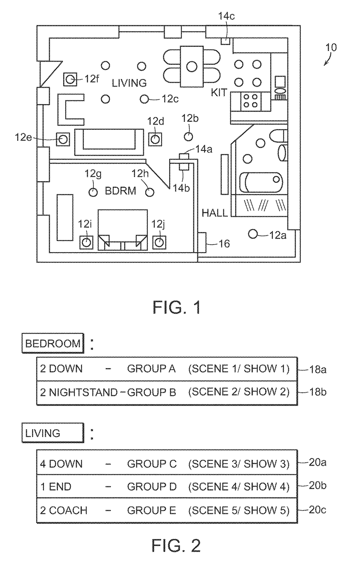
[0042]FIG. 1 illustrates an example of a residence 10 containing a plurality of physical lamps 12a, 12b, 12c, etc. The physical lamps are sometimes interchangeably referred to as simply lamps. Not all lamps are labeled for sake of brevity in the drawings. A residence may have numerous bedrooms, living rooms, rooms in general, and a significant number of lamps 12 can be arranged throughout that residence more or less than those shown in FIG. 1. Preferably, each lamp comprises at least one LED and a communication interface for a first communication protocol, that communication protocol being a wireless communication protocol used by all of the lamps 12 within, for example, residence 10. A popular first communication protocol can be WPAN using IEEE 802.15.4 and / or any protocol based thereon, like ZigBee. The lamps are arranged in the various rooms, and have a specified function based mostly upon their location. For example, lamps in the ceiling can be PAR lamps, whereas lamps in night ...


PUM


Abstract

A lighting control system and method is disclosed for not only controlling visual content loaded within a group set of illumination devices configured within a wireless network, but also for ensuring minimal control delay to those grouped devices. The lighting control system can include a lighting controller device that controls a plurality of lamps within a mesh network, not only to group those lamps but also to assign content to lamps within that group. The combination of a guaranteed groupcast to each of the group of lamps and an acknowledge back from those lamps that is aggregated over a single path achieves the improved lighting control system disclosed herein.

Description

CROSS REFERENCE TO RELATED APPLICATION[0001]This application is related to co-pending application filed concurrently herewith under Ser. No. 15 / 041,166, entitled “Device, System and Method for Controlling Visual Content Loaded Into A Grouped Set of Illumination Devices Configured Within A Wireless Network.”BACKGROUND OF THE INVENTION[0002]1. Field of the Invention[0003]This invention relates to illumination devices and, more particularly, to illumination devices interconnected by a network and controlled based on groupings of those devices and content stored therein.[0004]2. Description of the Relevant Art[0005]The following descriptions and examples are provided as background only and are intended to reveal information that is believed to be of possible relevance to the present invention. No admission is necessarily intended, nor should be construed, that any of the following information constitutes prior art impacting the patentable character of the subject matter claimed herein.[...

Claims


Application Information

Patent Timeline
Patent Type & Authority Patents(United States)
IPC IPC(8): H05B37/00H05B37/02H05B33/08H05B44/00
CPCH05B37/0272H05B33/0845H05B33/086H05B45/10H05B47/19H04W4/80H04W4/08H05B45/00H05B47/155G06F3/0484
Inventor HO, HORACE C.FRANK, REBECCAQUILLING, MARKHO, REBECCA M.SOOCH, NAV
Owner LUTRON TECH CO LLC
Why Eureka
Try Eureka