Utility knife

a utility knife and blade technology, applied in the field of utility knives, can solve the problems of different types of blades not being able to be used as required, and the positioning cannot be performed according to the extension length requirement of the blade, so as to achieve the effect of expanding the application scope of the utility knife, facilitating operation, and safe us

Active Publication Date: 2017-05-23
ZHEJIANG XINGDA STATIONERY
View PDF8 Cites 11 Cited by
  • Summary
  • Abstract
  • Description
  • Claims
  • Application Information

AI Technical Summary

Benefits of technology

[0004]It is an object of the present invention to provide a utility knife having safety in use and a double-blade switch. By this utility knife, different types of blades can be used as required; furthermore, positioning can be performed according to the extension length requirement of the blade.
[0016]Compared with the prior art, in the present invention, as there are two knife holders and blades, different blades may be used according to different requirements, so that the application scope of the utility knife is expanded greatly; meanwhile, the utility knife is safe in use and convenient in operation. The knife holder may be driven to slide forward as long as the corresponding push button is pressed down and pushed forward, and the blade attracted onto the corresponding knife holder is also extended out from the housing along with the knife holder; moreover, positioning may be performed, and a spare knife holder is provided so that the blades may be replaced in time. The utility knife with a nice appearance is safe in use and convenient in operation, and also has spare blades and a double-blade function, different blades may be used as required and quick blade replacement and positioning may be realized. The utility knife is reasonable and practical in structure.

Problems solved by technology

As a result, different types of blades cannot be used as required; furthermore, positioning cannot be performed according to the extension length requirement of the blade.

Method used


Image

  • Utility knife
  • Utility knife
  • Utility knife

Examples


Embodiment Construction

[0022]To enable a further understanding of the innovative and technological content of the invention herein refer to the detailed description of the invention and the accompanying drawings below:

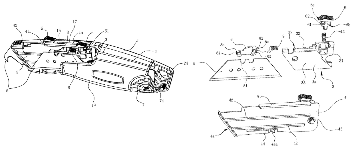
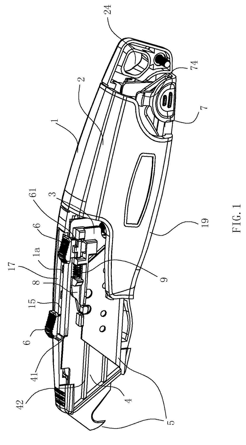
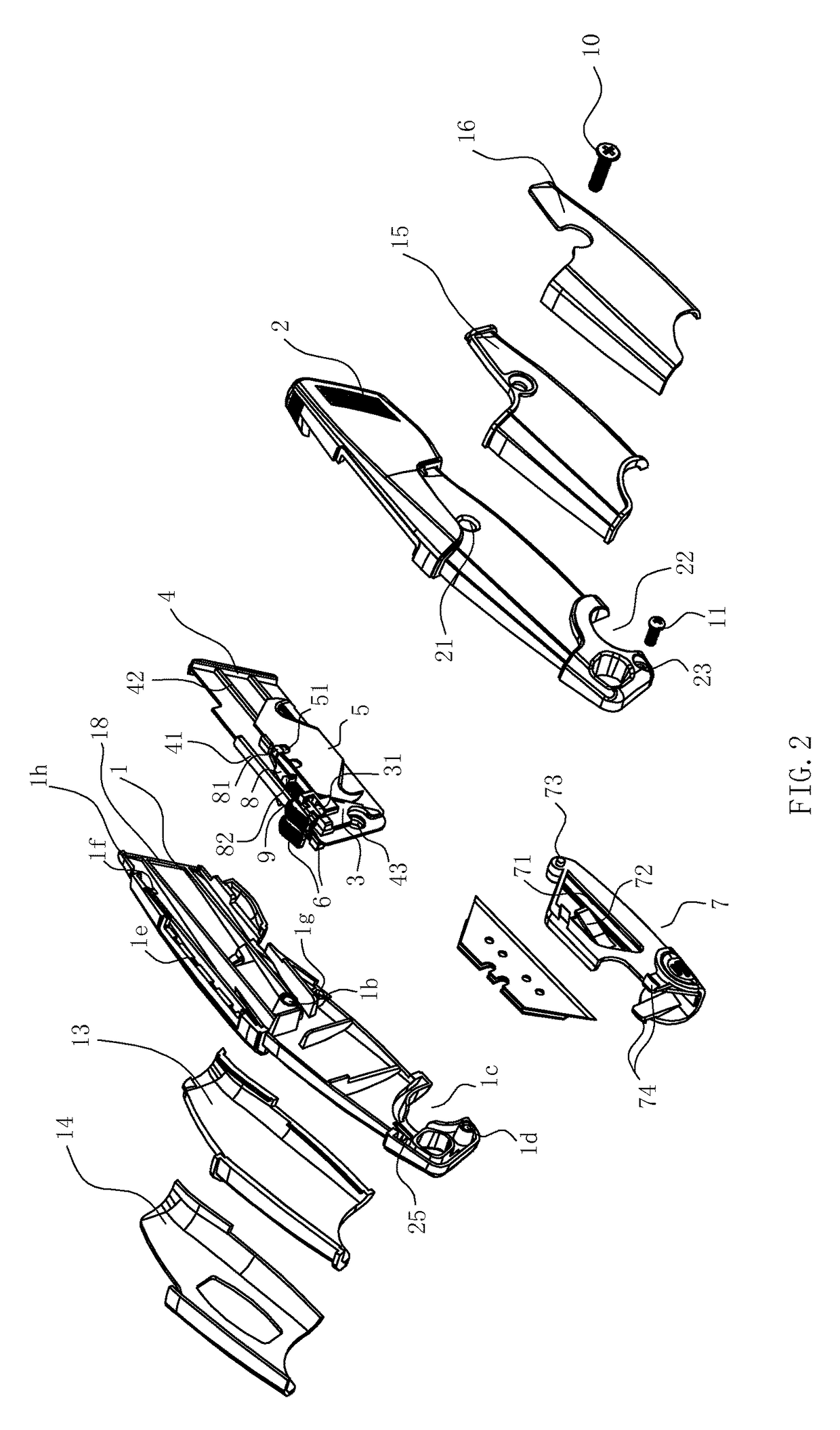
[0023]As shown in FIGS. 1 to 5, the utility knife comprises a housing 19, a knife holder gasket 4 disposed in the housing, two knife holders 3, two blades 5, two push buttons 6, a spare knife holder 7 and other main components.

[0024]The housing 19 is formed by an upper cover 2 and a base 1, which are made by aluminum die casting; after the upper cover 2 and the base 1 are mounted together, the housing has a head section with an opening 18 for blades to slide in and out of the housing; a strip-shaped aperture 17 is provided on top of the inner wall of the housing 19, four recesses 1a are respectively distributed inside two inner side wall of the strip-shaped aperture 17, that is, the top of the inner walls of the base 1 and upper cover 2; the knife holder gasket 4, made of stainless steel as ...


PUM


Abstract

A utility knife including a housing (19), two parallel knife holders slidingly disposed substantially parallel to each other inside the front section of the housing; different blades (5) are positioned on the two knife holders; each push button (6) is movably disposed on top of one knife holder (3); a strip-shaped aperture (17) is provided on top of the inner wall of the housing (19); the strip-shaped aperture has two grooves (1e), parallel to each other, for receiving the two push buttons and for allowing the two push buttons (6) to slide along the two parallel grooves; and a plurality of recesses (1a) are distributed inside each groove; each push button further comprises a snap block (61), when the snap block (61) is inserted into the corresponding recess (1a), the corresponding knife holder (3) and the blade (5) are locked in position.

Description

RELATE APPLICATIONS[0001]This application is a national phase entrance of and claims benefit to PCT Application for a utility knife, PCT / CN2012 / 000910, filed on Jul. 3, 2012, which claims benefit to Chinese Patent Application 201210134896.3, filed on May 3, 2012. The specifications of both applications are incorporated herein by this reference.FIELD OF THE INVENTION[0002]The present invention relates to a kind of a utility knife.DESCRIPTION OF THE PRIOR ART[0003]As one of common hand tools, utility knives are often used for cutting paper, leather, plastic sheets, hardboards or the like. There have been many types of utility cutters at present. For the convenience of replacement of blades, there are many utility knives with spare blades raised in the market. For example, a Chinese Patent (Patent No.: ZL200920117976.1), titled “UTILITY KNIFE WITH AUTOMATIC BLADE REPLACEMENT FUNCTION”, disclosed a utility knife comprising a housing and blades; a magnetic pushing block, capable of slidi...

Claims


Application Information

Patent Timeline
Patent Type & Authority Patents(United States)
IPC IPC(8): B26B5/00B26B1/08
CPCB26B5/001B26B1/08
Inventor WANG, AIGUO
Owner ZHEJIANG XINGDA STATIONERY
Why Eureka
Try Eureka