
Method and apparatus for measuring rail surface temperature

a surface temperature and rail technology, applied in the direction of pyrometry, optical radiation measurement, instruments, etc., can solve the problems of rail joints failing, track buckles, and is not easily accessible, and achieve the effect of non-conta

Active Publication Date: 2017-05-30
ENURGA
View PDF10 Cites 20 Cited by
  • Summary
  • Abstract
  • Description
  • Claims
  • Application Information

AI Technical Summary

Benefits of technology

[0010]A technical effect of the invention is that rail temperatures of long rail tracks are obtained from a stationary or moving rail car, providing the locomotive engineer with rail temperature information. Further the method and the apparatus of this invention provide non-contact, lower-cost alternatives to existing methods of tracking rail temperature across long rail roads.
[0011]Another technical effect of the invention is that the rail temperature is obtained without the need for assuming or fixing a value for the emissivity of the rail surface. This is advantageous since emissivity of the rail surface can vary from region to region and due to variations in material composition. The present invention is thus capable of providing more accurate temperature values compared to methods that use a fixed value for the emissivity of a rail surface.
[0012]Other aspects and advantages of this invention will be better understood from the following detailed description.

Problems solved by technology

Excessive tensile forces can cause rail joints to fail or pull apart in cold weather and high compressive forces affect lateral stability of a track and can cause the track to buckle.
Unfortunately, is not is easily obtainable when the rail is moving.
However, these instruments yield single point measurements, thereby requiring a prohibitively high number of them for monitoring any long section of a rail, which in turn, can be cost-prohibitive.
However, the lack of temporal and spatial resolution precludes their direct use in estimating rail temperatures from a moving rail vehicle.
In this portion of the infrared spectrum, dynamic range is limited, especially at lower temperatures.
If the emissivity value of the rail deviates the rail surface deviates from this fixed value, the temperature output by the sensor will be inaccurate.

Method used


Image

  • Method and apparatus for measuring rail surface temperature
  • Method and apparatus for measuring rail surface temperature
  • Method and apparatus for measuring rail surface temperature

Examples


Embodiment Construction

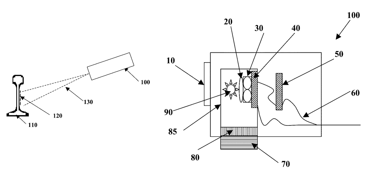
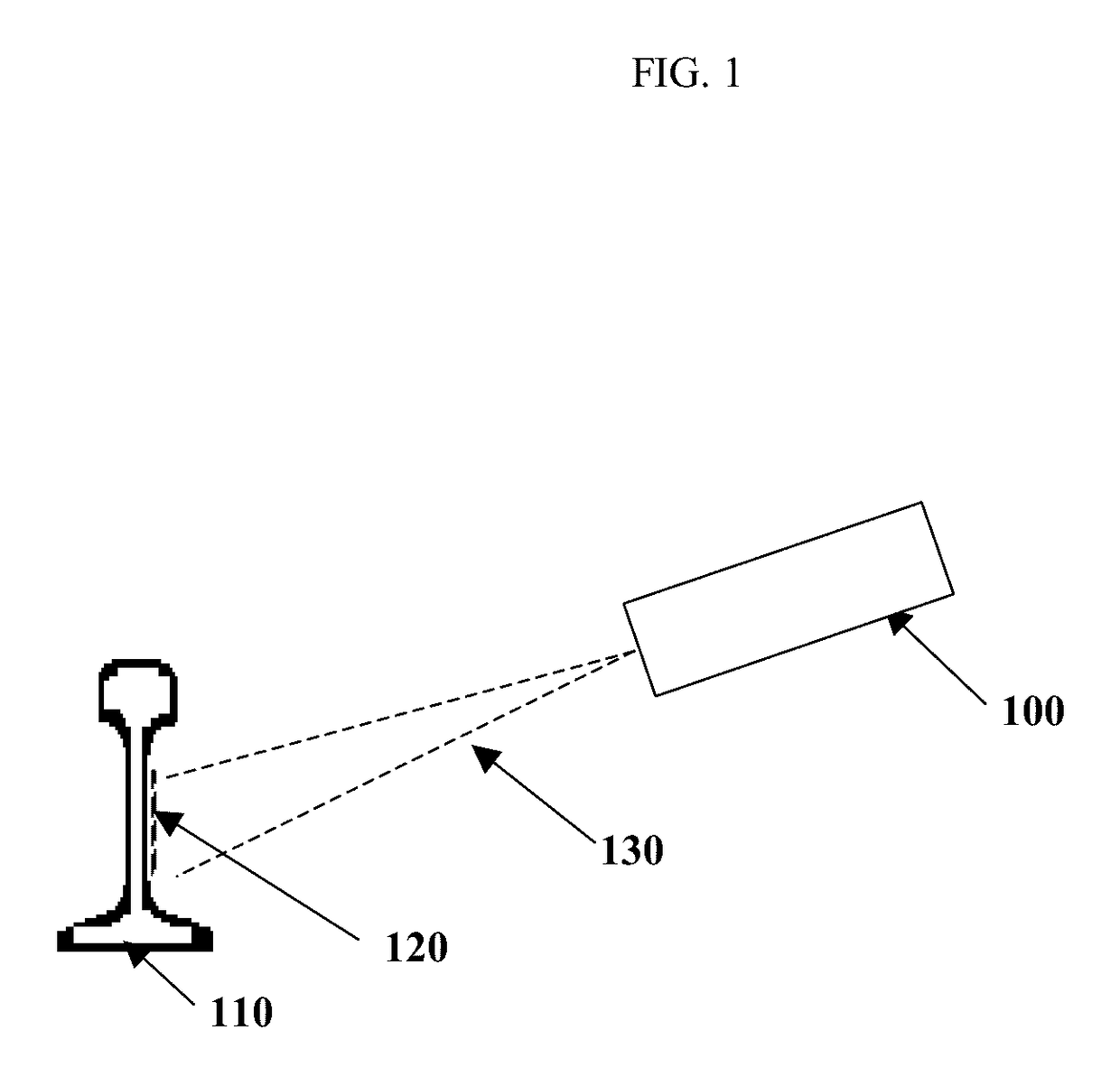
[0017]The present invention is directed to measuring temperature of a surface of a segment of a rail, hereinafter referred to as the temperature of the rail, from a stationary or a moving rail car. In this description, “a surface of a segment of a rail” and “rail” will be used interchangeably. The method measures the intensities of infrared radiation emitted by the rail and converts them to temperature of the rail utilizing relationships among the emissivity of rail surface, intensities of radiation at different wave lengths emitted by the rail, and the temperature of the rail. Measuring temperatures from the intensities of emitted radiation has been described in U.S. Pat. No. 6,111,151, U.S. Pat. No. 6,370,486, and U.S. Pat. No. 6,393,375 B1. The method of measuring the temperature of the rail will be explained with reference to FIGS. 1 through 4. FIG. 1 schematically represents a cross section of a rail 110, a side view of a segment 120 of the rail and a temperature sensor 100 whi...


PUM


Abstract

A method and apparatus suitable for measuring temperature of a surface of a segment of a rail using a sensor underneath a moving or a stationary rail car. The measurement is based on intensities of infrared radiation emitted by the surface. The method uses relationships among emissivity, radiation intensity and surface temperature without assuming an emissivity value for the surface. The apparatus comprises radiation detectors containing sensing elements, a lens system, and an analog to digital conversion board to convert radiation intensities to temperature.

Description

STATEMENT REGARDING FEDERALLY SPONSORED RESEARCH[0001]This work was supported by the United States Department of Transportation under Contract No. DTRT57-10-C-10083.CROSS REFERENCE TO RELATED APPLICATIONS[0002]This application claims the benefit of U.S. Provisional Application No. 61 / 699,928, filed Oct. 22, 2012, the contents of which are incorporated herein by reference.BACKGROUND OF THE INVENTION[0003]The present invention generally relates to measuring the temperature of a surface of a rail utilizing sensor or sensors embedded underneath of a stationary or moving rail car. The techniques utilized in this invention are useful in estimating the rail surface temperature to aid the locomotive engineer to make appropriate decisions taking into account rail surface temperatures prevailing at any given time and location.[0004]There is great interest in monitoring rail surface temperatures primarily as a mechanism to assure the safety of the railroads. In this discussion “rail temperatur...

Claims


Application Information

Patent Timeline
Patent Type & Authority Patents(United States)
IPC IPC(8): G01J5/00G01J5/06G01J5/12G01J5/08G01J5/52
CPCG01J5/0003G01J5/061G01J5/0806G01J5/0834G01J5/12G01J5/52G01J5/0804
Inventor SIVATHANU, YUDAYA RAJULIM, JONGMOOKNARAYANAN, VINOO
Owner ENURGA
Learn More