Laboratory centrifuge provided with means for the locking of a lid in its closed position

a technology for centrifuges and lids, which is applied in the direction of centrifuges, building locks, constructions, etc., can solve the problems of cumbersome structure of locking means, relative difficulty in respecting, and risk of locking position, so as to achieve optimal force for the locking of the lid, improve reliability, and simplify the effect of structur

Active Publication Date: 2017-06-06
AFI CENTRIFUGE
View PDF19 Cites 2 Cited by
  • Summary
  • Abstract
  • Description
  • Claims
  • Application Information

AI Technical Summary

Benefits of technology

[0031]This structural characteristic allows an optimal and rapid locking of the bolt in its closed position.
[0033]This direction of the opening force hence exerts a null lever arm on the actuating member about the motor axis of rotation, with a null moment on the motor axis, hence avoiding any phenomenon of rotation of the associated motor shaft.
[0034]This locking position is “wide” in that it makes a certain clearance possible, allowing a better taking into account of the inertia of the gear motors and a simpler adjustment.

Problems solved by technology

Now, in practice, this need for a precise alignment of three different points of the operating means makes such a structure relatively complex; further, the alignment of the three points is relatively difficult to respect due to the inertia of the gear motors, with a risk about the holding in position of the locking.
Moreover, this structure of the locking means is cumbersome due to the presence of the connecting rod interposed between the bolt and the eccentric.
This mechanism is also complex as regards the number of parts, with the resulting problems of reliability and of holding of the locking.
The operation of the bolts, through such a structure of the locking means, further proves to be relatively slow.

Method used


Image

  • Laboratory centrifuge provided with means for the locking of a lid in its closed position
  • Laboratory centrifuge provided with means for the locking of a lid in its closed position
  • Laboratory centrifuge provided with means for the locking of a lid in its closed position

Examples


Embodiment Construction

[0049]The invention will be further illustrated, without being limited in anyway, by the following description of a particular embodiment, in relation with the appended drawings in which:

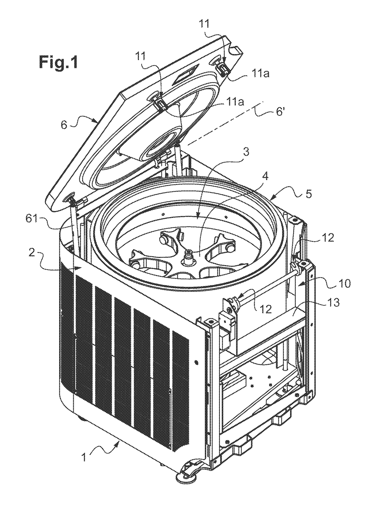
[0050]FIG. 1 is a general view of a laboratory centrifuge according to the invention, in which the lid is shown in the open position and in which a front wall of the casing is not shown so as to offer a visual access to the means that allow the locking of this lid in the closed position;

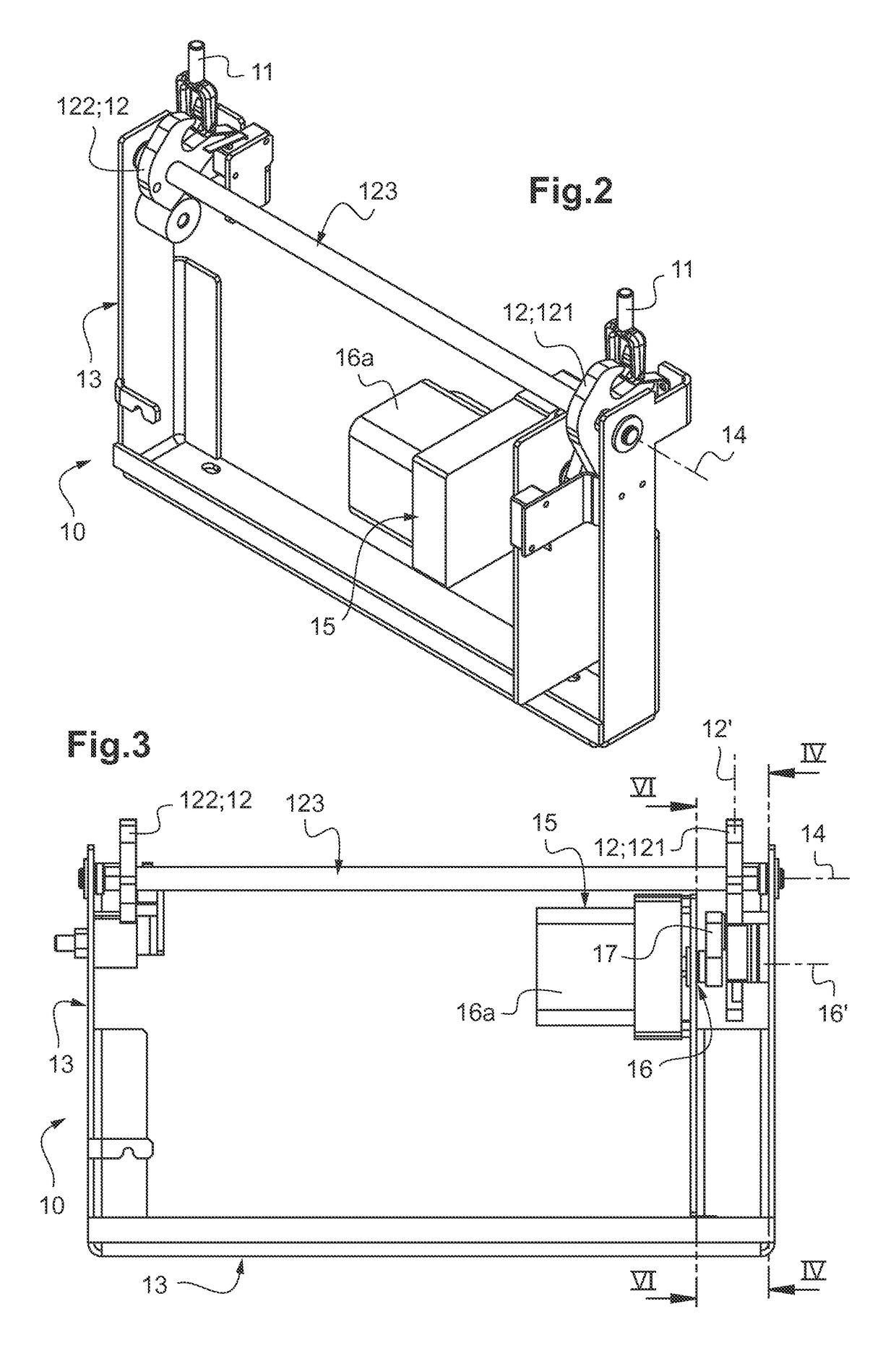
[0051]FIG. 2 shows, in a perspective view, the locking means of the centrifuge according to FIG. 1;

[0052]FIG. 3 is a front view of the locking means according to FIG. 2;

[0053]FIG. 4 is a cross-sectional view of FIG. 3, according to a cutting plane IV-IV passing through the axis of rotation of the bold and extending perpendicular to the latter;

[0054]FIG. 5 is a partial and enlarged view of FIG. 4, showing its bolt and the associated operating means;

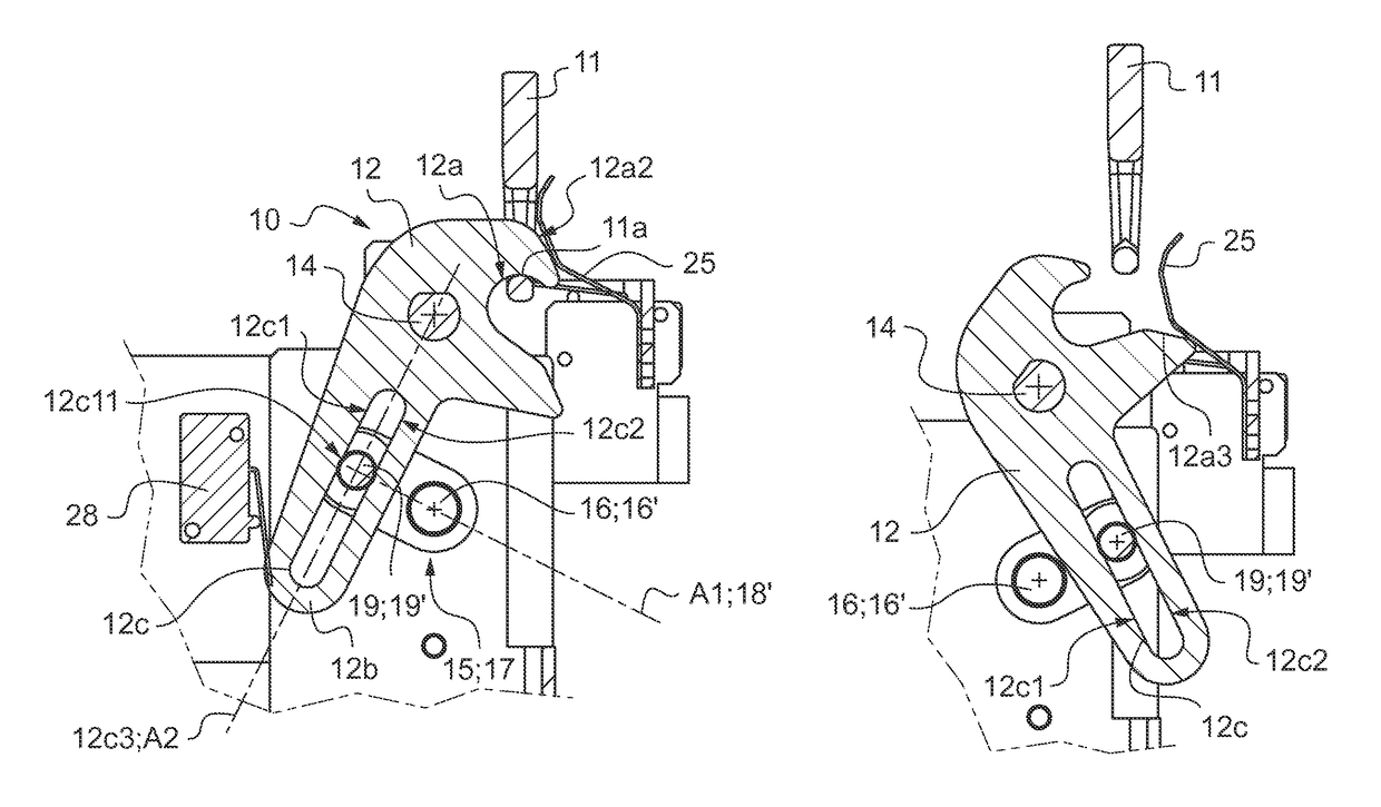
[0055]FIG. 6 is also a cross-sectional view of FIG. 3, according to a ...


PUM


Abstract

A laboratory centrifuge includes elements (10) for the locking of a lid in a closed position, which locking elements (10) include at least one strike (11) and at least one bolt (12) mobile between a locking position and an unlocking position. These locking elements (10) also include operating elements (15) including a motor shaft (16) that is coupled to the bolt (12) through transmission elements (17). The transmission elements (17) include a crank (18), extending the motor shaft (16), which carries an actuating member (19) bearing on a contact surface (12c1, 12c2) formed on the bolt (12), so that the driving into eccentric rotation of the actuating member (19) about the motor axis of rotation (16′) causes its circulation and bearing along the contact surface (12c1, 12c2) and the rotational control of the bolt (12) between its locking and unlocking positions.

Description

TECHNICAL FIELD TO WHICH THE INVENTION RELATES[0001]The present invention relates to the general field of the laboratory centrifuges, for separating the components contained in a liquid through a phenomenon of centrifugation.TECHNOLOGICAL BACKGROUND[0002]Centrifugation allows to separate components of very variable size and mass contained in a liquid sample, from molecules to entire cells.[0003]Indeed, the putting into rotation of a rotor carrying a container containing this liquid sample generates a centrifugal force that produces an acceleration that is exerted radially outwardly of the axis of rotation.[0004]Hence, for a given component, by choosing correctly the speed of rotation, the acceleration obtained becomes predominant with respect to the molecular agitation, which causes its settling to the bottom of the container or its rising up to the surface.[0005]For the implementation of this technique, a laboratory centrifuge is used, which comprises:[0006]a driving shaft, associa...

Claims


Application Information

Patent Timeline
Patent Type & Authority Patents(United States)
IPC IPC(8): B04B7/06E05B47/00E05B17/00B04B7/02B04B9/08
CPCB04B9/08B04B7/02B04B7/06E05B17/0025E05B47/0012B04B2009/085E05B2047/0069
Inventor LE GUYADER, PHILIPPELETOURNEUR, JEAN-CLAUDEROLLAND, NORBERT
Owner AFI CENTRIFUGE
Why Eureka
Try Eureka