Unlock instant, AI-driven research and patent intelligence for your innovation.

Power amplifier and power amplification method

a power amplifier and power amplifier technology, applied in the direction of rf amplifiers, amplifiers with semiconductor devices/discharge tubes, high frequency amplifiers, etc., can solve the problems of low efficiency and efficiency reduction, and achieve the effect of reducing reflected waves

Active Publication Date: 2017-06-06
NEC CORP
View PDF11 Cites 3 Cited by
  • Summary
  • Abstract
  • Description
  • Claims
  • Application Information

AI Technical Summary

Benefits of technology

[0016]According to the present invention, it is possible to reduce reflected waves of fundamental waves generated in one of or both a carrier amplifier and a peak amplifier that are connected in parallel and to match an impedance of a Doherty amplifier with a desired value.

Problems solved by technology

Therefore, as there is almost no time for the power amplifier to operate near a saturated output at which the power amplifier can relatively maintain to be highly efficient, the power amplifier is used with low efficiency.
The efficiency is reduced to some extent due to a limited loss of an N-way splitter.

Method used


Image

  • Power amplifier and power amplification method
  • Power amplifier and power amplification method
  • Power amplifier and power amplification method

Examples


first embodiment

[0026]A power amplifier 100 according to a first embodiment will be described below. FIG. 1 is a block diagram schematically showing a configuration of the power amplifier 100 according to the first embodiment. The power amplifier 100 is configured as a power amplifier including a so-called Doherty amplifier. In this embodiment, an example in which the power amplifier 100 includes a Doherty amplifier 101 and a transmission line L12 will be described. The Doherty amplifier 101 is configured to include a carrier amplifier unit 1, a peak amplifier unit 2, a dividing unit 3, a combining unit 4, and a transmission line L11. When high power is requested for the power amplifier 100, both the carrier amplifier unit 1 and the peak amplifier unit 2 are used to amplify power. On the other hand, when the power amplifier 100 operates with low power, the power amplifier 100 stops the peak amplifier unit 2, and only the carrier amplifier unit 1 is used to amplify the power. Thus, the power amplifi...

second embodiment

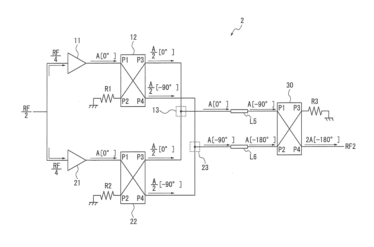
[0086]Next, a power amplifier 200 according to a second embodiment will be described. The power amplifier 200 has the same configuration as that of the power amplifier 100 shown in FIG. 1. The power amplifier 200 is configured in such a way that the peak amplifier unit 2 includes a plurality of amplifiers. As the configuration of the power amplifier 200 other than the peak amplifier unit 2 is the same as that of the power amplifier 100, a description of the configuration of the power amplifier 200 other than the peak amplifier unit 2 will be omitted.

[0087]FIG. 7 is a block diagram schematically showing a configuration of the peak amplifier unit 2 of the power amplifier 200 according to the second embodiment. As shown in FIG. 7, the peak amplifier unit 2 of the power amplifier 200 can have the same configuration as that of the peak amplifier unit 2 of the power amplifier 100.

[0088]According to this configuration, in a manner similar to the first embodiment, it can be understood that ...


PUM


Abstract

In dividing units, signals propagating between input ports- and output ports and between input ports and output ports have phases shifted by 90° from phases of signals propagating between the input ports and the output port and between the input ports and the output ports. Amplifiers output amplified signals that are in phase to the dividing units. A combining and dividing unit outputs a combined signal obtained by combining signals from the output ports of the dividing units to an input port of a combining unit. A combining and dividing unit outputs a combined signal obtained by combining signals from the output ports of the dividing units to an input port of a combining unit.

Description

[0001]This application is a National Stage Entry of PCT / JP2013 / 006691 filed on Nov. 14, 2013, the contents of all of which are incorporated herein by reference, in their entirety.TECHNICAL FIELD[0002]The present invention relates to a power amplifier and a power amplification method.BACKGROUND ART[0003]Recently, there has been a demand for communication systems with improved efficiency. For example, linearity and high efficiency are desired for power amplifiers that are used in radio communication systems. Recent communication systems using multi-value digital modulation often use signals each having an average value of a signal amplitude that greatly differs from a maximum value of the signal amplitude. When such signals are amplified by a normal power amplifier, it is necessary to set an operating point of the amplifier so that the signals can be amplified to a maximum amplitude without a distortion. Therefore, as there is almost no time for the power amplifier to operate near a s...

Claims


Application Information

Patent Timeline
Patent Type & Authority Patents(United States)
IPC IPC(8): H03F3/19H03F1/02H03F3/24H03F3/60H03F3/21
CPCH03F1/0288H03F3/19H03F3/211H03F3/245H03F3/602H03F2200/192H03F2200/198H03F2200/204H03F2200/451H03F2203/21142
Inventor OTAKE, SUMITAKA
Owner NEC CORP