Electrical connector assembly having contacts configured for high-speed signal transmission

a technology of high-speed signal transmission and connector assembly, which is applied in the direction of connection contact member material, fixed connection, coupling device connection, etc., can solve the problems of increasing the difficulty of installing contacts, complicated ground means and signal contacts manufacturing, and difficult to build suitable electrical connectors for the apparatus. , to achieve the effect of simplifying the structure and enhancing the electrical performan

Inactive Publication Date: 2005-09-27
HON HAI PRECISION IND CO LTD
View PDF7 Cites 11 Cited by
  • Summary
  • Abstract
  • Description
  • Claims
  • Application Information

AI Technical Summary

Benefits of technology

[0010]It is therefore an object of the present invention to provide an electrical connector assembly for high-speed signal transmission which has a simplified structure and enhanced electrical performance.
[0015]Due to the wide interval between adjacent signal contacts, cross-talk between adjacent signal contacts can be reduced. In addition, the signal contacts are well shielded by the ground contacts and the shield-joint contacts. This significantly facilitates suppression of any EMI noise emanating from these signal transmission paths. Furthermore, because the distances between the paired signal contacts is increased, the impedance of the first and second connectors increases at the same time in order to match impedance of the signal circuitry at other electronic components along the same signal transmitting paths.

Problems solved by technology

The faster the signal transmission required of an electronic apparatus, the harder it is to build suitable electrical connectors for the apparatus.
In addition, manufacturing of the ground means and signal contacts becomes significantly complicated due to the different structural designs of the signal contacts and ground means.
Furthermore, the increased number of contacts results in more difficulty when installing the contacts into the connector housing, because only a smaller pitch between every two adjacent receiving holes in the housing is available.
These difficulties in manufacturing increase costs significantly, and do not necessarily guarantee better electrical performance.

Method used


Image

  • Electrical connector assembly having contacts configured for high-speed signal transmission
  • Electrical connector assembly having contacts configured for high-speed signal transmission
  • Electrical connector assembly having contacts configured for high-speed signal transmission

Examples


Embodiment Construction

[0028]Reference will now be in detail to the preferred embodiments of the present invention.

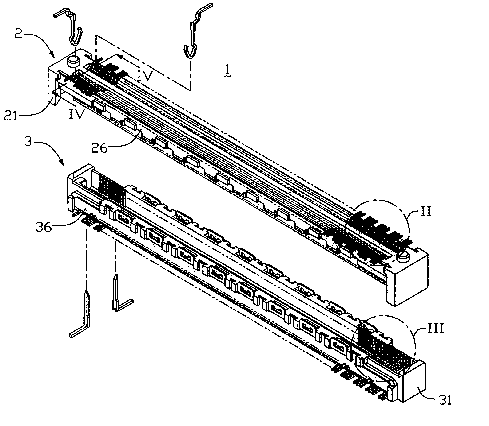
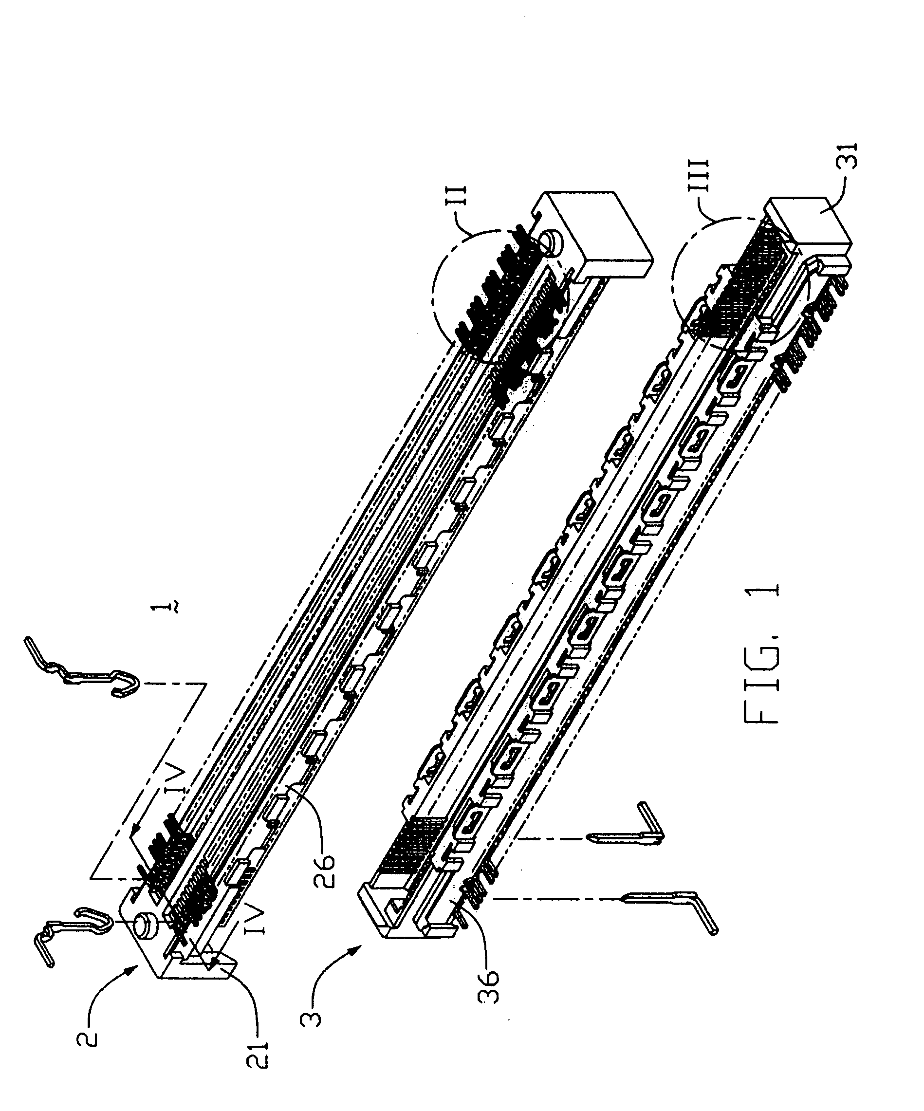
[0029]It should be noted that for a better understanding of the invention, most like components are designated by like reference numerals throughout the various figures of the embodiments. Referring to FIGS. 1 to 4, an electrical connector assembly 1 in accordance with a first preferred embodiment of the present invention includes a first board-to-board connector 2 and a second board-to-board connector 3 adapted to mate with each other.

[0030]The first connector 2, a receptacle one of the assembly, includes a first insulative housing 21 receiving a multiplicity of first contacts 22, and two first shield plates 26 separately attached on each of two lengthwise exterior surfaces of the first housing 21. The first housing 21 defines a first mounting surface 211 seated on a printed circuit board (not shown), and a first mating surface 212 opposite to the first mounting surface 211 and facing toward...


PUM


Abstract

An electrical connector assembly (1) includes a first connector (2) and a second connector (3). The first connector includes a first housing (21) and first electrical contacts (22). The second connector includes a second housing (31) and second electrical contacts (32). The first contacts include signal contacts (22A), ground contacts (22B), and shield-joint contacts (22C). The signal contacts are arranged in pairs, with each pair transmitting one set of differential signals. The signal contacts within each pair are separated by an empty passage (214). Adjacent pairs of signal contacts are separated by one ground contact or by one shield-joint contact. The second contacts are configured to correspond to the first contacts, so that the first and second contacts can electrically mate with each other to electrically interconnect the first and second connectors. The wide interval between adjacent signal contacts enables cross talk between adjacent signal contacts to be reduced.

Description

CROSS-REFERENCE TO RELATED APPLICATIONS[0001]This is a continuation application of a copending patent application Ser. No. 10 / 329,022, filed Dec. 23, 2002, now U.S. Pat. No. 6,783,400.BACKGROUND OF THE INVENTION[0002]1. Field of the Invention[0003]The present invention relates to electrical connector assemblies, and more particularly to a connector assembly having two mating connectors used for high-speed signal transmission.[0004]2. Description of Related Art[0005]High-speed digital electronic apparatus, such as certain communication equipments and computer servers, require fast and accurate signal transmission. These apparatus have electronic components including connectors, wires, circuit boards, and integrated circuit packages. In low-speed applications, these components can function normally in cooperation with each other. However, in high-speed applications, conductivity and other electrical characteristics of these components become critical in ensuring that the electrical pe...

Claims


Application Information

Patent Timeline
Patent Type & Authority Patents(United States)
IPC IPC(8): H01R13/658
CPCH01R12/57H01R12/716H01R13/6471H01R13/6477H01R13/6585
Inventor WU, MIN-FANGYU, HUNG-CHI
Owner HON HAI PRECISION IND CO LTD
Why Eureka
Try Eureka