
Guide tool for resection of patellofemoral joint

a technology for resection and guide tools, which is applied in the direction of bone drill guides, surgical saws, medical science, etc., can solve the problems of high surgical demands, inability for surgeons to achieve perfect fit, and difficulty in achieving free hand removal of significant bone areas, etc., and achieve the effect of compromising the overall stability of the tool

Active Publication Date: 2017-06-13
BIOMET UK HEALTHCARE
View PDF40 Cites 1 Cited by
  • Summary
  • Abstract
  • Description
  • Claims
  • Application Information

AI Technical Summary

Benefits of technology

The patent describes a tool for resecting bone pieces and implanting prosthesis. The tool has a plate with matching edges to the prosthesis, allowing the surgeon to visualize where the prosthesis will rest on the bone surface. The tool also has a window with a locating feature, such as notches, that can help visualize the same area. Furthermore, the tool may have redundant fixation openings, which provide additional options for the surgeon to secure the tool in place. These features improve the accuracy and stability of the tool and ultimately improve the outcome of the surgery.

Problems solved by technology

It is not possible to replicate such a surface using free hand tools, and hence such conventional methods do not enable a surgeon to achieve a perfect fit between resected bone surface and prosthetic implant.
In addition, the free hand removal of a significant area of bone is highly surgically demanding.

Method used


Image

  • Guide tool for resection of patellofemoral joint
  • Guide tool for resection of patellofemoral joint
  • Guide tool for resection of patellofemoral joint

Examples


Embodiment Construction

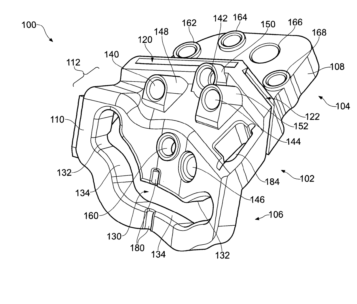
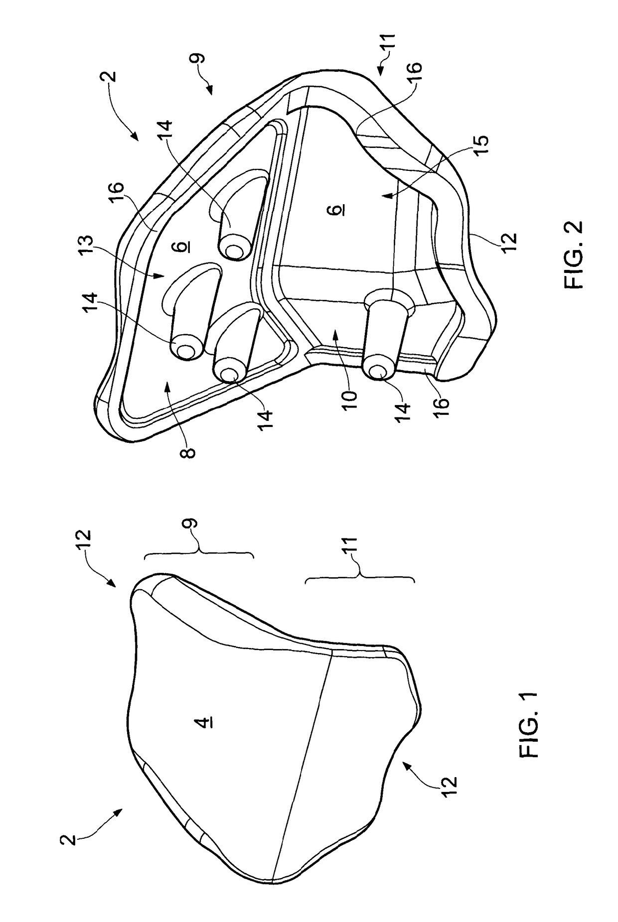
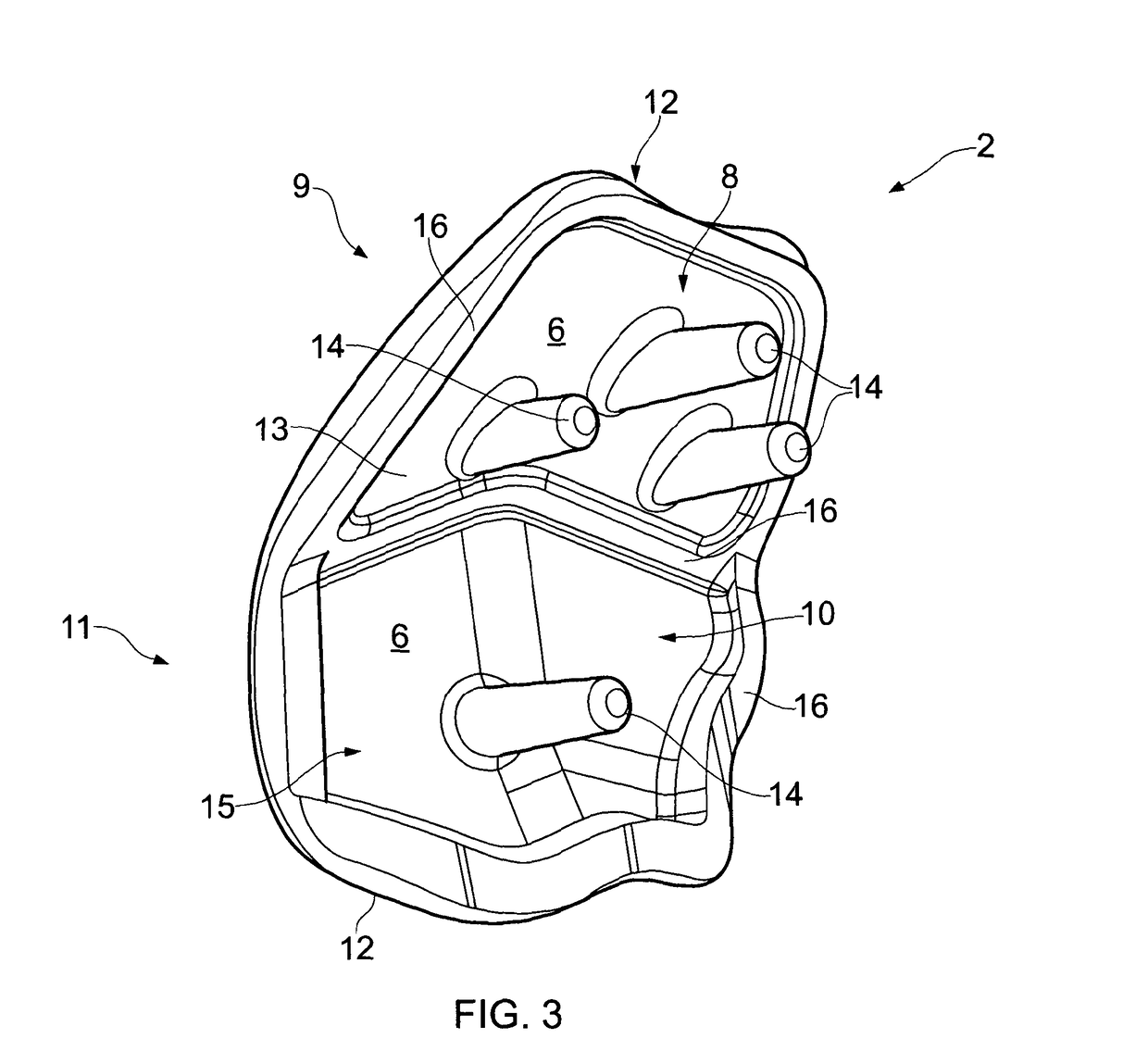
[0041]A femoral resurfacing prosthesis 2 for a patellofemoral joint is illustrated in FIGS. 1 to 3. The prosthesis 2 comprises an articulating surface 4 that is shaped to articulate with a patella resurfacing prosthesis or natural patella (not shown) and a bone engaging surface 6. The bone engaging surface is designed to rest adjacent a resected distal femoral surface and may be cemented in place. It will be appreciated that the bone engaging surface 6 is a relatively complex surface, varying in three dimensions. The surface 6 comprises a first substantially planar part 8 and a second substantially “V” shaped part 10, the two parts 8, 10 of the bone engaging surface 6 corresponding to anterior 9, and posterior 11 regions of the prosthesis 2 respectively. Each part 8, 10 of the bone engaging surface may be slightly recessed, with a protruding border 16 around its periphery. The recessed surfaces 8, 10 and borders 16 define two shallow recesses 13, 15 within which bone cement may be l...


PUM


Abstract

A guide tool (100) for guiding resection of a bone piece, comprising a body (102), a burr guide opening (130) extending through the body (102) and defining a burr resection surface, and a saw guide opening (120) extending through the body (102) and defining a saw resection surface, the burr guide opening (130) and the saw guide opening (120) being aligned such that the burr resection surface and the saw resection surface intersect, defining a bone piece resection surface.

Description

CROSS-REFERENCE TO RELATED APPLICATIONS[0001]This application is a 371 U. S. National Stage of International Application No. PCT / GB2012 / 050583, filed on Mar. 16, 2012 and published as WO 2012 / 123758 A1 on Sep. 20, 2012. This application claims priority to British Patent Application No. 1104510.1, filed on Mar. 17, 2011. The disclosures of the above applications are incorporated herein by reference in their entirety.[0002]The present invention relates to a guide tool and particularly although not exclusively to a guide tool for guiding resection of the distal femur prior to implantation of a femoral resurfacing prosthesis for the patellofemoral joint.BACKGROUND[0003]Joint resurfacing operations require the removal or resection of outer layers of bone, some or all of which may be diseased or degraded, in order to allow the implantation of a resurfacing prosthesis. The resurfacing prosthesis includes a bone engaging surface, that contacts and may be cemented to the exposed bone surface...

Claims


Application Information

Patent Timeline
Patent Type & Authority Patents(United States)
IPC IPC(8): A61B17/17A61B17/15A61F2/38
CPCA61B17/1764A61B17/155A61F2/3877A61B17/14A61B17/154A61B17/15A61B17/56
Inventor MURRAYDODDLLOYD, RUSSELLRIDLEY, DUNCAN ANDREWTHOMAS, WILLIAM KEITH
Owner BIOMET UK HEALTHCARE
Learn More