Radio frequency (RF) birdcage coil with separately controlled ring members and rungs for use in a magnetic resonance (MR) imaging system

Active Publication Date: 2015-10-01
KONINKLJIJKE PHILIPS NV
View PDF4 Cites 60 Cited by
  • Summary
  • Abstract
  • Description
  • Claims
  • Application Information

AI Technical Summary

Benefits of technology

[0006]It is therefore an object of the invention to provide a radio frequency (RF) antenna device for applying an RF field to an examination space of a

Problems solved by technology

RF currents flowing in these loops can be controlled but mutual coupling may lead to hi

Method used


Image

  • Radio frequency (RF) birdcage coil with separately controlled ring members and rungs for use in a magnetic resonance (MR) imaging system
  • Radio frequency (RF) birdcage coil with separately controlled ring members and rungs for use in a magnetic resonance (MR) imaging system
  • Radio frequency (RF) birdcage coil with separately controlled ring members and rungs for use in a magnetic resonance (MR) imaging system

Examples


Example

[0042]This description contains several embodiments of the invention. The individual embodiments are described with reference to particular groups of figures and are identified by a prefix number of the particular embodiment. Features whose function is the same or basically the same in all embodiments are identified by reference numbers made up of the prefix number of the embodiment to which it relates, followed by the number of the feature.

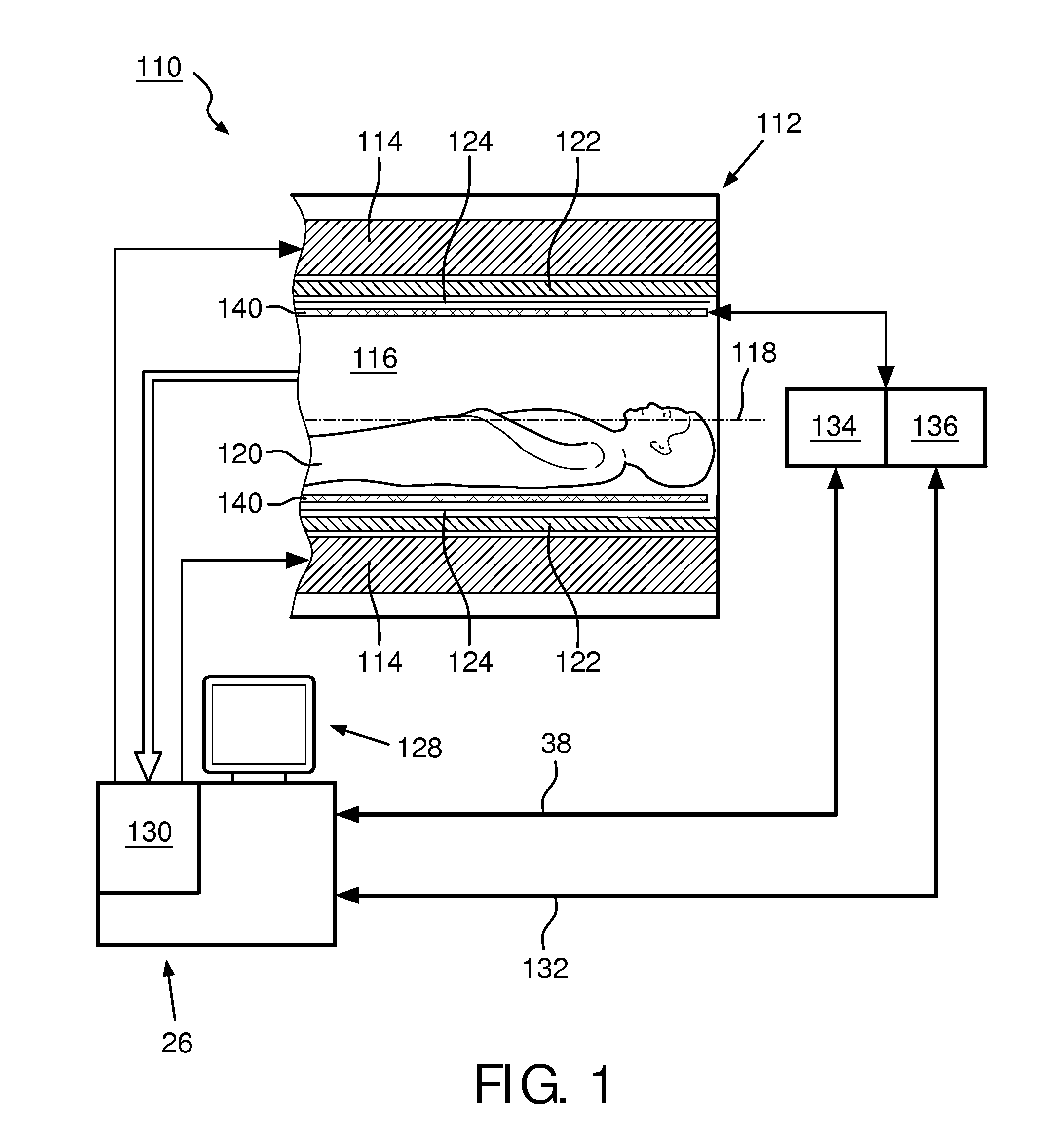
[0043]FIG. 1 shows a schematic illustration of a part of an embodiment of a magnetic resonance (MR) imaging system 110 comprising an MR scanner 112. The MR imaging system 110 includes a main magnet 114 provided for generating a substantially static magnetic field. The main magnet 114 has a central bore that provides an examination space 116 around a center axis 118 for a subject of interest 120, usually a patient, to be positioned within. In principle, the invention is also applicable to any other type of MR imaging system providing an examinatio...


PUM


Abstract

A radio frequency (RF) antenna device (40) for applying an RF field to an examination space (16) of a magnetic resonance (MR) imaging system (10), the RF antenna device (40) comprising a plurality of rungs (42, 44) arranged substantially parallel and in an azimuthally substantially equally spaced relationship along an outside of a virtual cylinder (50) with a cylinder axis (52) running parallel to main directions of extension (48); at least one transversal antenna member (54) electromagnetically coupled to at least one rung (42, 44) of the plurality of rungs (42, 44), wherein the at least one transversal antenna member (54) is arranged within a plane substantially perpendicular to the main directions of extension (48) of the plurality of rungs (42, 44); and a plurality of RF circuitries (62, 64, 66), wherein at least one RF circuitry (62, 64, 66) is provided for each rung (42, 44) of the plurality of rungs (42, 44) for mutual decoupling and for individually feeding RF power into and for the at least one transversal antenna member (54) for individually feeding RF power into.

Description

FIELD OF THE INVENTION[0001]The invention pertains to a radio frequency (RF) antenna device for applying an RF field to an examination space of a magnetic resonance (MR) imaging system, and an MR imaging system employing at least one such RF antenna device.BACKGROUND OF THE INVENTION[0002]In the field of magnetic resonance (MR) imaging, and in particular for multi-transmit MR imaging applications, it is known to especially use two types of degenerate radio frequency (RF) coils as antennae for exciting nuclear spins within a subject of interest, usually a patient, and detecting signals from them. These antennae, birdcage coil and transverse electromagnetic (TEM) coil, are widely used for MR imaging in the very-high RF band (VHF) and are being introduced in commercial 3 T whole-body MR imaging scanners. The birdcage coil has multiple conductor rungs which are arranged around an examination region of the MR imaging scanner, extending parallel to a main magnetic field direction. The coi...

Claims


Application Information

Patent Timeline
IPC IPC(8): G01R33/34G01R33/36H01Q7/00
CPCG01R33/34076H01Q7/00G01R33/3614G01R33/3628G01R33/365G01R33/5659
Inventor LEUSSLER, CHRISTOPHWUELBERN, JAN HENDRIK
Owner KONINKLJIJKE PHILIPS NV
Why Eureka
Try Eureka