Magnetic resonance imaging apparatus and gradient magnetic field coil

Inactive Publication Date: 2009-03-12
HITACHI LTD
View PDF11 Cites 22 Cited by
  • Summary
  • Abstract
  • Description
  • Claims
  • Application Information

AI Technical Summary

Benefits of technology

[0013]According to the gradient magnetic field coil of the invention, a circuit pattern is formed on an electrically conductive plate having such a shape that an imaging space in which an examinee is disposed can be broadly secured, and then the electrically conductive plate is deformed or processed, whereby a gradien

Problems solved by technology

However, in this case, the static magnetic field generating efficiency is lowered and thus large magnetomotive force is needed.
Therefore, the cost of a magnet is increased.
However, in this case, the interval be

Method used


Image

  • Magnetic resonance imaging apparatus and gradient magnetic field coil
  • Magnetic resonance imaging apparatus and gradient magnetic field coil
  • Magnetic resonance imaging apparatus and gradient magnetic field coil

Examples


first embodiment

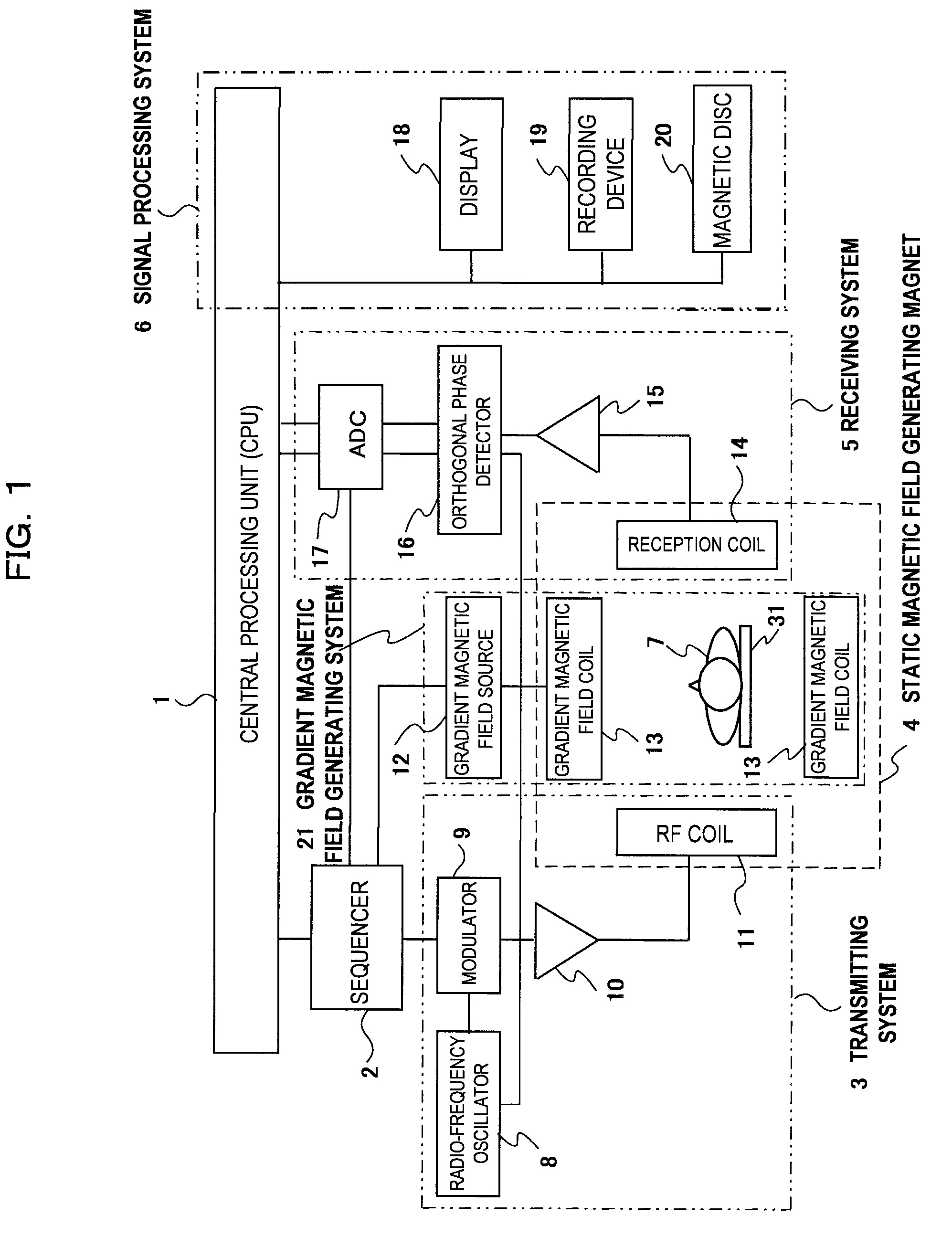
[0037]As shown in FIG. 1, an MRI apparatus of an embodiment of the invention has a static magnetic field generating magnet 4, a gradient magnetic field generating system 21, a bed 31 disposed in an imaging space while an examinee 7 is mounted thereon, a transmitting system 3 for applying a radio-frequency magnetic field to the examinee 7, a receiving system 5 for receiving an NMR signal generated by the examinee 1, a sequencer 2, a signal processing system 6 and a central processing unit (CPU) 1.

[0038]The static magnetic field generating magnet 4 generates uniform static magnetic field in the body axis direction of the examinee 7 or in a direction orthogonal to the body axis direction in an imaging space. For example, a magnetic field generating apparatus based on any one of permanent magnet type, a normal conduction type and a superconduction type may be used. The transmitting system 3 contains a radio-frequency oscillator 8, a modulator 9, a radio-frequency amplifier 10 and a radi...

second embodiment

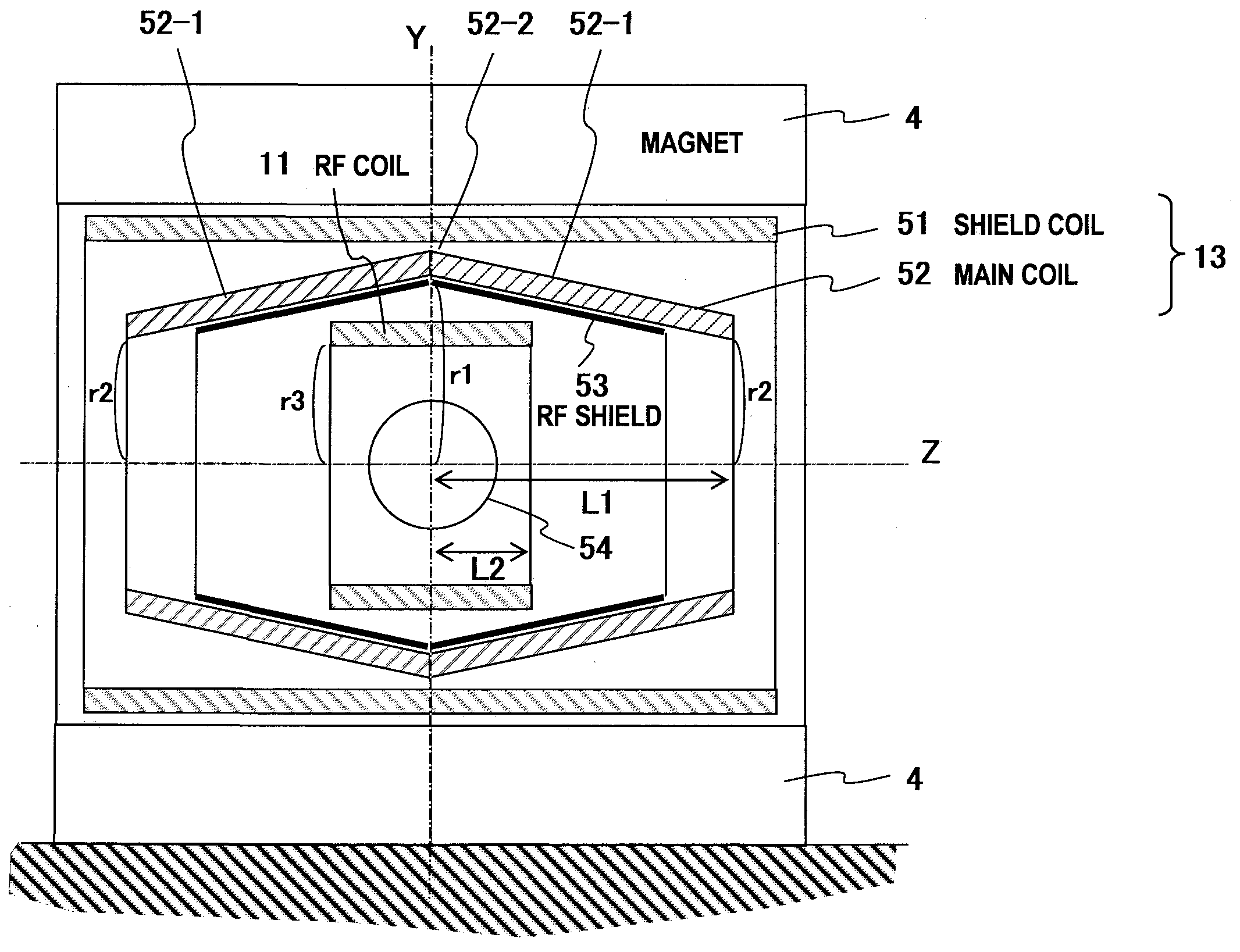
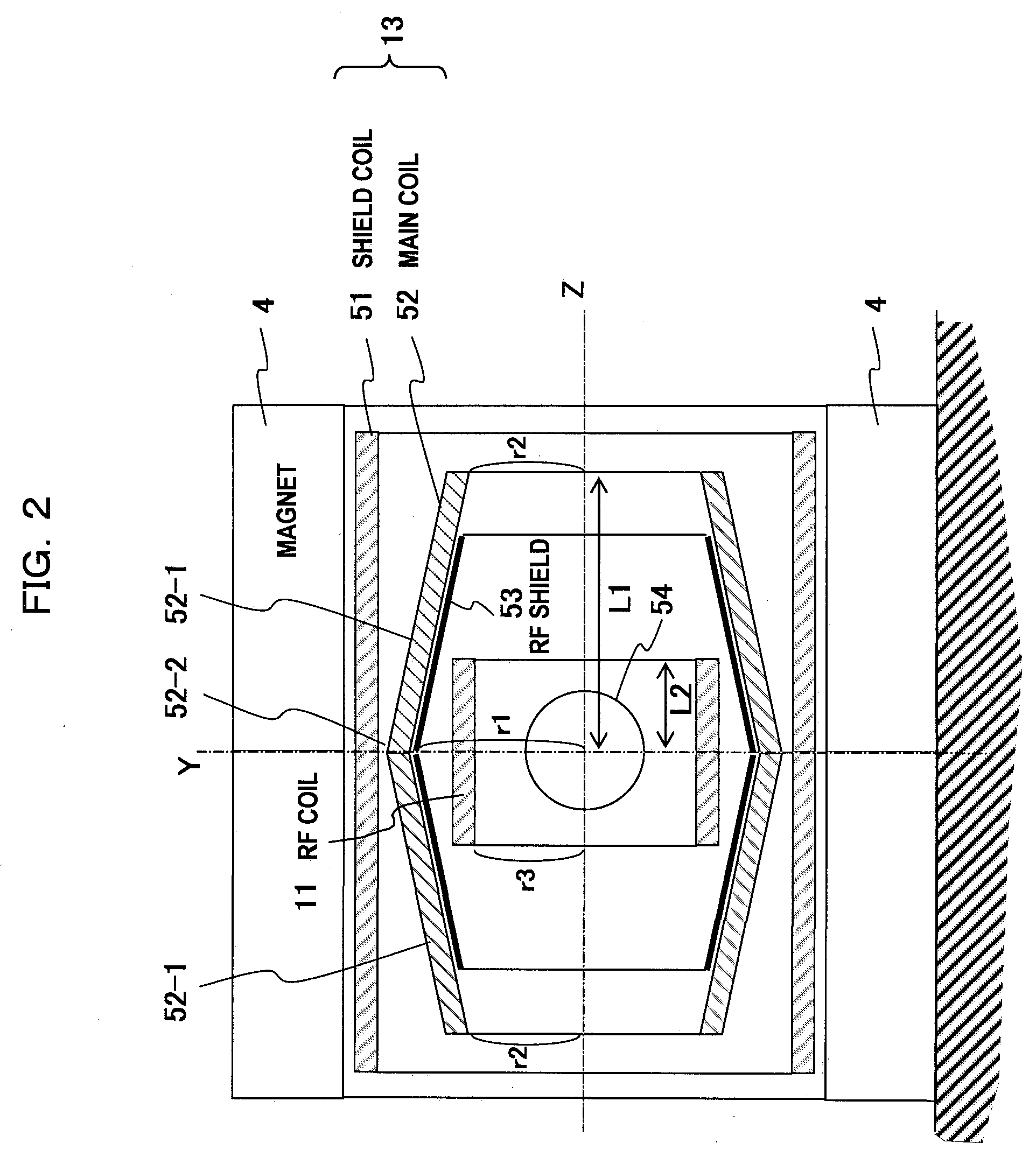
[0075]A second embodiment according to the invention will be described with reference to FIGS. 5 to 8. The second embodiment is identical to the first embodiment in that the center portion 52-2 (Z=0) of the main coil 52 is recessed and the radius r2 of the center portion 52-2 is larger than the radius r1 of the end portions, however, it is different from the first embodiment in that the main coil 52 is divided into a cylindrical member 52-1 (side portion) of radius r1 and a cylindrical member 52-2 (center portion) of radius r2. Accordingly, the radius of the main coil 52 is reduced stepwise (in a staircase pattern) with the approach from the center portion Z=0 to the end portions Z=L1.

[0076]That is, in the gradient magnetic field coil comprising the main coil 52 for generating the gradient magnetic field in the imaging space and the shield coil 51 for generating the magnetic field cancelling the leak magnetic field from the main coil 52 to the opposite side to the imaging space, the...

third embodiment

[0093]A vertical (or horizontal) magnetic field type MRI apparatus in which respective pairs of magnets 4, gradient magnetic field coils 13 and RF coils 11 are disposed so as to sandwich an imaging space 54 therebetween will be described as a third embodiment with reference to FIG. 9. In FIG. 9, the elements having the same actions as the constituent elements of FIG. 2 of the first embodiment are represented by the same reference numerals.

[0094]In the third embodiment of the invention, as shown in FIG. 9, the magnets 4, the shield coils 51 and the RF coils 11 are respectively designed in the form of paired disc shape. The pair of main coils 52 confront each other through the imaging space, and each of them is designed in a conical surface (cone side surface) shape. Accordingly, the interval between the pair of main coils 52 is largest at the center portion 52-2 of the imaging space (Z=0), and continuously reduced with the shift to the end portions of the side portions 52-1 of the ma...


PUM


Abstract

An MRI apparatus excellent in magnetic field generation efficiency is provided. According to this invention, a main coil (52) of a gradient magnetic field coil (13) is partially recessed to reduce the total thickness of a radio-frequency coil (11) and a gradient magnetic field coil (13). That is, the main coil (52) is designed in a tubular shape, and the diameter r1 at the center portion of the imaging space is larger than the diameter r2 of the main coil end portion. Accordingly, the RF coil (11) can be disposed to be near to the gradient magnetic field coil (13) side without lowering the magnetic field generation efficiency.

Description

TECHNICAL FIELD[0001]The present invention relates to a magnetic resonance imaging (hereinafter referred to as MRI) apparatus, and particularly to a gradient magnetic field coil with which an imaging space in which an examinee is disposed can be secured as a large space and which can be easily manufactured, and an MRI apparatus having the gradient magnetic field coil.BACKGROUND ART[0002]An MRI apparatus measures a signal obtained from a nuclear magnetic resonance (hereinafter referred to as “NMR”) phenomenon of an examinee disposed under a static magnetic field, and subjects the signal to calculation processing to display images of a density distribution, a relaxation time distribution, etc. of nuclear spins in the examinee as tomograms, and it is used for various kinds of diagnosis, etc. while targeting human bodies as examinees.[0003]In the MRI apparatus, an examinee is disposed in a static magnetic field space (imaging space) having spatially and timely uniform intensity and dire...

Claims


Application Information

Patent Timeline
IPC IPC(8): G01R33/385
CPCG01R33/385G01R33/3856G01R33/422G01R33/4215G01R33/3858
Inventor YATSUO, TAKESHITAKEUCHI, HIROYUKIKUROME, AKIRA
Owner HITACHI LTD
Why Eureka
Try Eureka