Multi-zone oven with variable cavity sizes

a multi-zone oven and cavity technology, applied in the field of convection ovens, can solve the problems of uneven cooking of food items placed high and low speed air flow uneven heating of heated air in the oven cavity, etc., and achieve the effect of prolonging the cooking tim

Active Publication Date: 2017-06-13
ALTO SHAAM
View PDF448 Cites 29 Cited by
  • Summary
  • Abstract
  • Description
  • Claims
  • Application Information

AI Technical Summary

Benefits of technology

[0020]The oven may also have a sensor for detecting the opening of oven doors during a cook cycle. To compensate for any disruption to the cook cycle due to the opened oven door, the oven's controller may extend the cooking time(s) or re-adjust cooking parameters for the cooking chamber(s) based on the measured amount of time the oven doors were kept open during their respective cook cycles.

Problems solved by technology

One problem with the heating system of a conventional convection oven is that it can generate regions of high and low speed air flow in the oven cavity such that the heated air is not uniformly distributed within the oven cavity.
As a result, food items placed in the oven cavity may be cooked unevenly.
In addition, food items placed on the same rack may not receive uniform heating either.
This unevenness of cooking can result in food waste, as food items located in the higher heat portions of the oven cavity can be unacceptably overdone as compared to the food items located in the lower heat portions.
Conventional convection ovens have other problems as well.
For example, only one cook temperature and heat transfer profile, such as blower speed, can be delivered in a conventional convection oven at any one time, thereby limiting the types of foods that can be cooked simultaneously.
This can be overcome by having multiple convection ovens set at different cook temperatures and heat transfer profiles, but doing so will result in space and energy inefficiency.

Method used


Image

  • Multi-zone oven with variable cavity sizes
  • Multi-zone oven with variable cavity sizes
  • Multi-zone oven with variable cavity sizes

Examples


Embodiment Construction

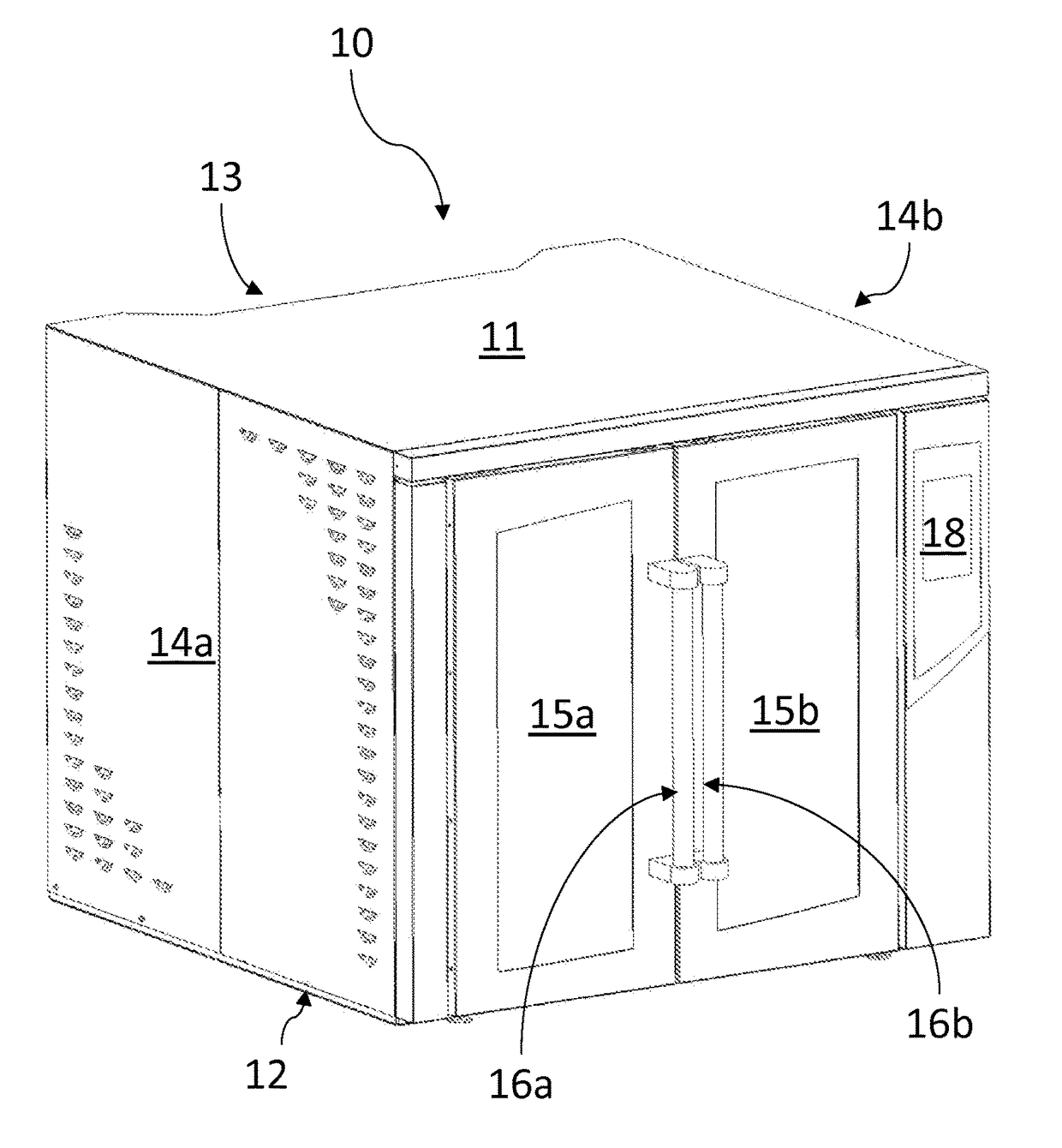
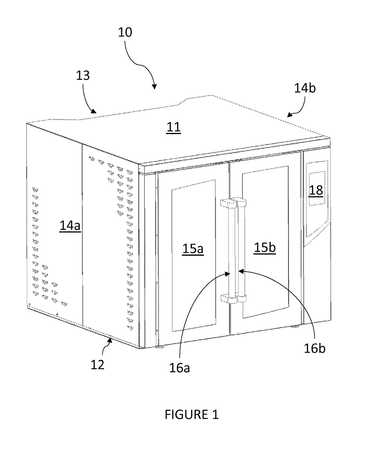
[0031]Referring now to the drawings and in particular to FIG. 1, there is depicted an isometric view of a convection oven, in accordance with an exemplary embodiment of the present invention. As shown, a convection oven 10 includes a housing having a top panel 11, a bottom panel 12, a rear panel 13 and two side panels 14a, 14b.

[0032]A pair of oven doors 15a, 15b may form the front panel of the housing and are pivotally connected with side panels 14a, 14b, respectively, via hinges. Oven doors 15a and 15b may include handles 16a and 16b, respectively, for opening and closing the same, and a latch may be provided to keep doors 15a, 15b in a closed position. Door sensing switches (not shown) may be placed so as to sense when doors 15a, 15b are being opened or closed.

[0033]In alternative embodiments, instead of a pair of oven doors, the oven may include a single oven door which is pivotally connected with one of side panels 14a, 14b, top panel 11, or bottom panel 12 via hinges.

[0034]Con...


PUM


Abstract

A convection oven is disclosed. The convection oven comprises a housing having an oven cavity and an oven door for access to the oven cavity, at least one air blower for generating heated air, one or more air channels for directing the heated air from the air blower toward the oven cavity, and one or more removable air plenums, wherein each removable air plenum is connected to one of the one or more air channels, comprises an air intake edge for receiving the heated air from the air channel, defines the top or the bottom of a cooking chamber within the oven cavity, and comprises a plurality of air vents for directing the heated air into the cooking chamber. The convection oven may further comprise a control panel for separately and independently controlling each of the cooking chambers defined by the removable air plenums.

Description

FIELD OF INVENTION[0001]The present invention relates to cooking ovens in general, and in particular to a convection oven having removable air plenums.BACKGROUND OF THE INVENTION[0002]An oven generally includes an oven cavity configured to receive food articles for cooking. The oven also includes a heating element, which can be an electric resistance element or a gas burner, for generating heat energy to cook any food items placed within an oven cavity. Some ovens may include a fan for forcing movement of heated air within the oven cavity, and those ovens are commonly referred to as convection ovens.[0003]Convection ovens have been the workhorse in commercial kitchens for many decades. Commercial convection ovens generally come in two sizes, namely, full-size and half-size. Full-sized commercial convection ovens are designed to fit within the space of an industry standard footprint, which is approximately 40 inches wide by 40 inches deep, made available for full-sized convection ove...

Claims


Application Information

Patent Timeline
Patent Type & Authority Patents(United States)
IPC IPC(8): F24C15/32A21B1/26F24C15/16F24C15/00
CPCF24C15/322A21B1/26F24C15/16F24C15/00F24C15/007A21B1/245F24C15/32F24C15/166F24C15/327F24C15/18A21B3/04
Inventor MCKEE, PHILIP R.VANLANEN, LEE THOMASCOLEMAN, TODD
Owner ALTO SHAAM
Why Eureka
Try Eureka