Vehicular display apparatus

a technology of display apparatus and display screen, which is applied in the direction of picture reproducers using projection devices, static indicating devices, instruments, etc., can solve the problems of not facilitating achieve the effect of facilitating the discernment of an image, and facilitating the preservation of an installation spa

Active Publication Date: 2017-06-13
DENSO CORP
View PDF13 Cites 4 Cited by
  • Summary
  • Abstract
  • Description
  • Claims
  • Application Information

AI Technical Summary

Benefits of technology

[0008]The above configuration switches the display by the first optical system and the display by the second optical system to enable to display a virtual image or real image of a display image at a position at which an occupant of a vehicle can easily discern the image. Further, the distance between the light source unit and the first projection surface is made smaller than the distance between the light source unit and the second projection surface; this accomplishes the downsizing that facilitates preserving an installation space. Thus, a vehicular display apparatus can be provided which attains both easiness in discernment of a display image and easiness in preservation of the installation space.

Problems solved by technology

This may not facilitate preserving of an installation space.

Method used


Image

  • Vehicular display apparatus
  • Vehicular display apparatus
  • Vehicular display apparatus

Examples


first embodiment

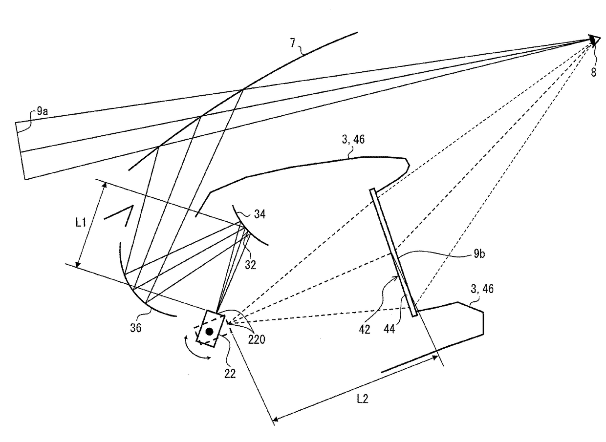
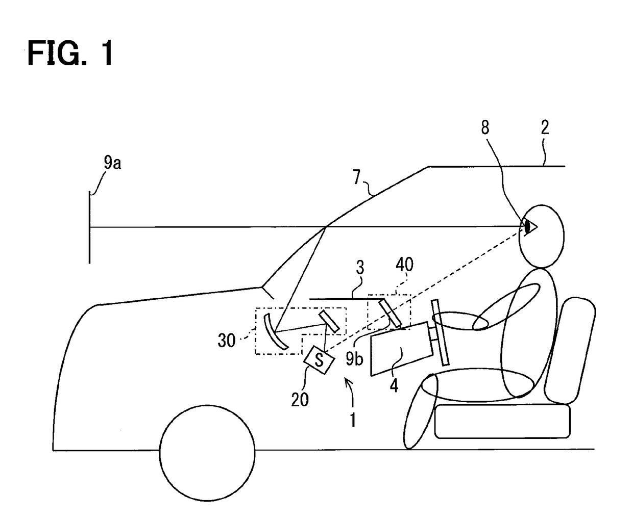
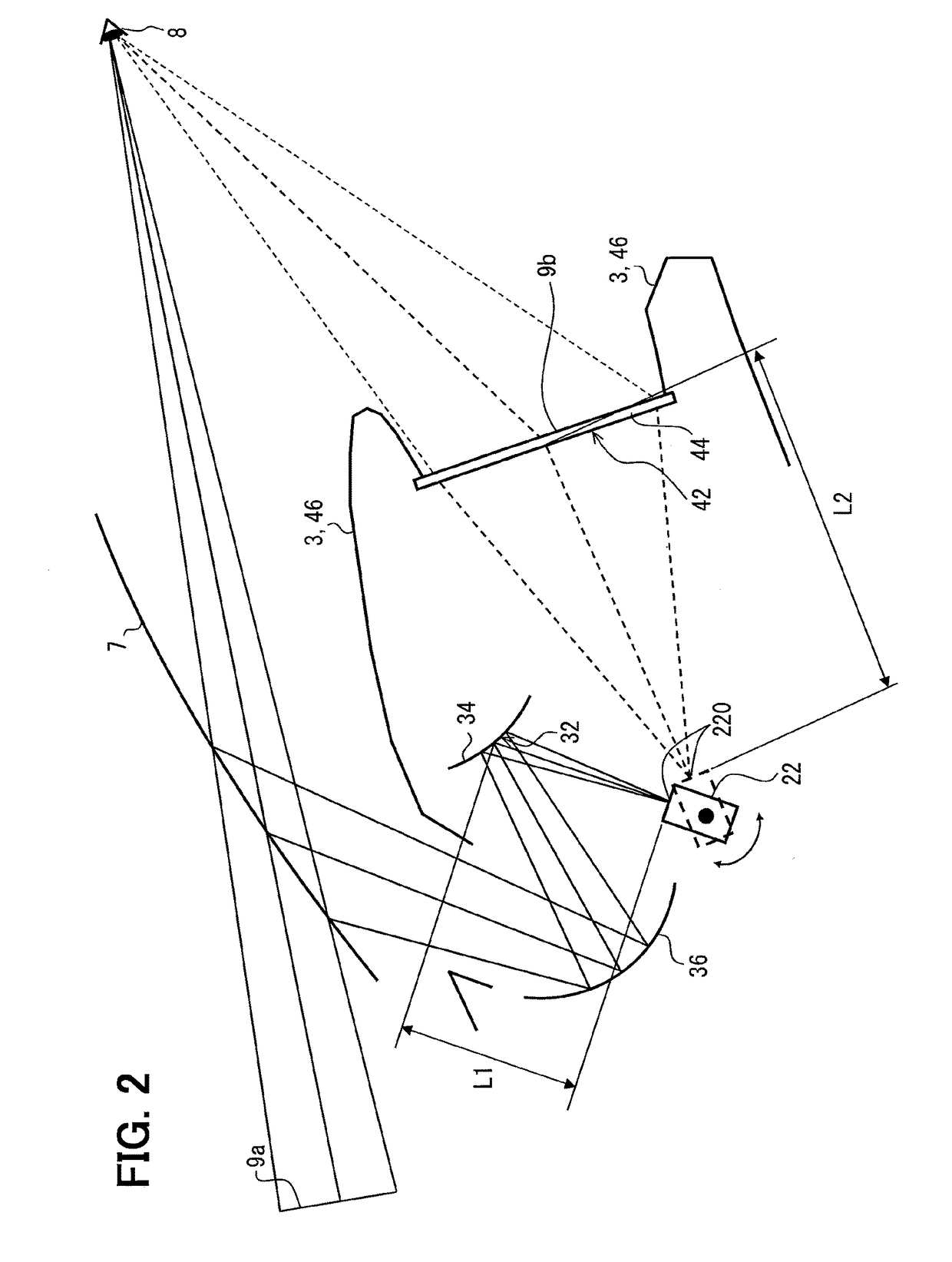
[0020]As shown in FIG. 1, a vehicular display apparatus 1 according to a first embodiment of the present disclosure is installed in a vehicle 2 (may be referred to as a host vehicle 2), and stowed in an instrument panel 3. A first optical system 30 of the vehicular display apparatus 1 displays a virtual image 9a of a display image so as to discern the virtual image inside the vehicle 2 through the medium of a windshield 7 of the vehicle 2. More particularly, light reflected from the windshield 7 reaches an eye point 8 of an occupant of the vehicle 2 (hereinafter, referred to as a vehicle occupant). The vehicle occupant perceives the light reaching the eye point 8, and discerns the virtual image 9a of the display image formed in front of the windshield 7.

[0021]The windshield 7 of the vehicle 2 is formed like a plate with a translucent glass substrate, and is retained as an integral part of the vehicle 2. The windshield 7A has an interior-side surface on which a display image is proje...

second embodiment

[0071]As in FIG. 9, a second embodiment of the present disclosure is a variant of the first embodiment.

[0072](Concrete Configuration)

[0073]The concrete configuration of the second embodiment will be described mainly about a point different from the first embodiment.

[0074]A switching mechanism 2050 of the present embodiment is provided as shown in FIG. 9. Here, switching display by the first optical system 30 and display by the second optical system 40 is implemented by the controller 10 and switching mechanism 2050. A combination of the controller 10 and switching mechanism 2050 may be referred to as a switching section, switching device, or switching means. The switching mechanism 2050 drives and turns a screen member 2034 in response to a driving signal from the electrically connected controller 10. The screen member 2034 can be turned on, for example, an axis of rotation that extends in the lateral direction of the vehicle 2 and is attached to the upper part of the member 2034. D...


PUM


Abstract

A vehicular display apparatus includes a light source unit that emits laser light; a first optical system that uses a first projection surface, onto which a display image is projected, to make a virtual image discernible; a second optical system that uses a second projection surface, onto which the display image is projected, to make a real image discernible; a controller; and a switching mechanism that switch the two optical systems. The distance between the light source unit and first projection surface is smaller than the distance between the light source unit and second projection surface.

Description

CROSS REFERENCE TO RELATED APPLICATION[0001]The present disclosure is a U.S. national stage application of PCT / JP2014 / 000299 filed on Jan. 22, 2014 and is based on Japanese Patent Application No. 2013-10517 filed on Jan. 23, 2013, the disclosures of which are incorporated herein by reference.TECHNICAL FIELD[0002]The present disclosure relates to a vehicular display apparatus, which is installed in a vehicle and provides a display image.BACKGROUND ART[0003]There is conventionally proposed a vehicular display apparatus that switches (i) virtual image display displaying a virtual image of a display image to be discernible inside a vehicle, and (ii) real image display displaying a real image of the display image to be discernible inside the vehicle. For example, Patent Literature 1 discloses a vehicular display apparatus that switches the virtual image display and real image display through swiveling of a display body itself which presents the display image.PRIOR ART LITERATURESPatent L...

Claims


Application Information

Patent Timeline
Patent Type & Authority Patents(United States)
IPC IPC(8): G02B27/01H04N9/31B60K35/00G09G3/00
CPCG02B27/0101B60K35/00G02B27/01H04N9/3129B60K2350/2056B60K2350/2065G02B2027/0141G02B2027/0147G02B2027/0165G02B2027/0198G09G3/002G09G2380/10B60K37/02B60K2370/333B60K2370/334B60K2370/1529B60K2370/1534B60K2370/31B60K2370/347G09G3/025G09G3/3413G09G2360/04G09G5/36
Inventor KANAMORI, NAOHITO
Owner DENSO CORP
Why Eureka
Try Eureka