
System for composite marine propellers

a composite marine and propeller technology, applied in the direction of rotary propellers, machine/engines, vessels, etc., can solve the problems of reducing the efficiency of the propeller assembly, requiring a more powerful drive, and premature failure of the propeller blades

Active Publication Date: 2017-06-20
GENERAL ELECTRIC CO
View PDF24 Cites 0 Cited by
  • Summary
  • Abstract
  • Description
  • Claims
  • Application Information

AI Technical Summary

Benefits of technology

The patent text describes a propeller assembly with blades that can be easily attached and detached from a central hub. The blades have a dovetail that fits into a wedge on the hub, and the dovetail has a bearing that engages with the wedge during use. The blades can be adjusted for different loads by adjusting the clearance between the dovetail and the wedge. The technical effect of this design is that it allows for easy replacement of blades without having to remove the entire hub, which saves time and resources.

Problems solved by technology

Such stress can result in premature failure of the propeller blades or may require the propeller blades to be heavier and more robust, thereby requiring a more powerful drive and decreasing the efficiency of the propeller assembly.

Method used


Image

  • System for composite marine propellers
  • System for composite marine propellers
  • System for composite marine propellers

Examples


first embodiment

[0028]FIG. 5 is a first detail 501 depicting the engagement between first dovetail sidewall 401 and undercut sidewall 130. In first detail 501, first dovetail sidewall 401 includes a first dovetail portion 550A corresponding to bearing portion 410 and a second dovetail portion 552A corresponding to clearance portion 412. Second dovetail portion 552A is linearly divergent from undercut sidewall 130, thereby defining a clearance gap 554A between first dovetail sidewall 401 and undercut sidewall 130.

second embodiment

[0029]FIG. 6 is a second detail 502 depicting the engagement between first dovetail sidewall 401 and undercut sidewall 130. In second detail 502, first dovetail sidewall 401 includes a first dovetail portion 550B corresponding to bearing portion 410 and a second dovetail portion 552B corresponding to clearance portion 412. Second dovetail portion 552B is concavely arcuately divergent from undercut sidewall 130, thereby defining a clearance gap 554B between first dovetail sidewall 401 and undercut sidewall 130.

third embodiment

[0030]FIG. 7 is a third detail 503 depicting the engagement between first dovetail sidewall 401 and undercut sidewall 130. In third detail 503, first dovetail sidewall 401 includes a first dovetail portion 550C corresponding to bearing portion 410 and a second dovetail portion 552C corresponding to clearance portion 412. Second dovetail portion 552C is linearly divergent from undercut sidewall 130 at two distinct angles, thereby defining a clearance gap 554C between first dovetail sidewall 401 and undercut sidewall 130.


PUM


Abstract

A propeller assembly includes a central hub including a first forward-facing end, a second aft-facing end, a hub body extending therebetween, and a plurality of channels spaced circumferentially around the central hub. The propeller assembly further includes blade wedges configured to be inserted into and to retain blades within the channels of the central hub. Each blade includes a blade dovetail including a dovetail face configured to engage a respective channel sidewall and / or a respective wedge sidewall. The dovetail face includes a bearing portion that engages the respective channel sidewall and / or the respective wedge sidewall and a clearance portion that is spaced from the respective channel sidewall and / or the respective wedge sidewall by a clearance gap during a first loading of the propeller assembly and that engages the respective channel sidewall or wedge sidewall during a second loading, the second loading greater than the first loading.

Description

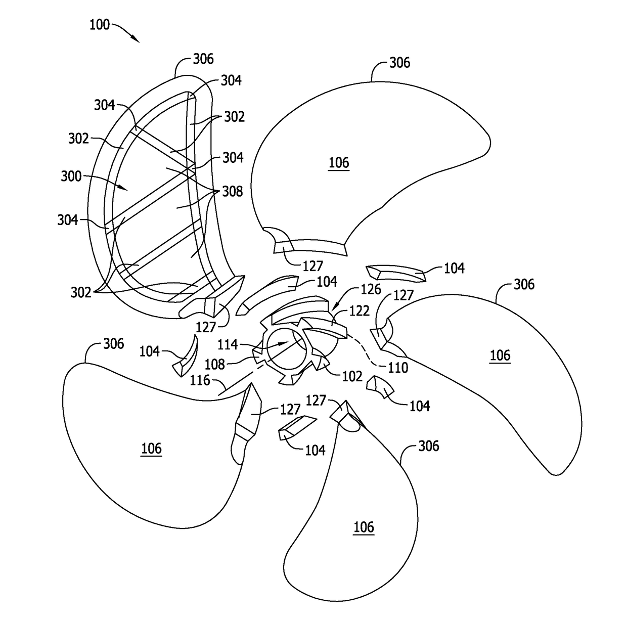
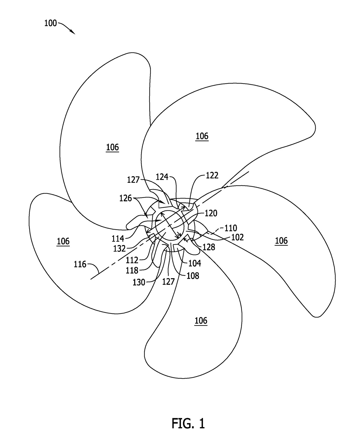
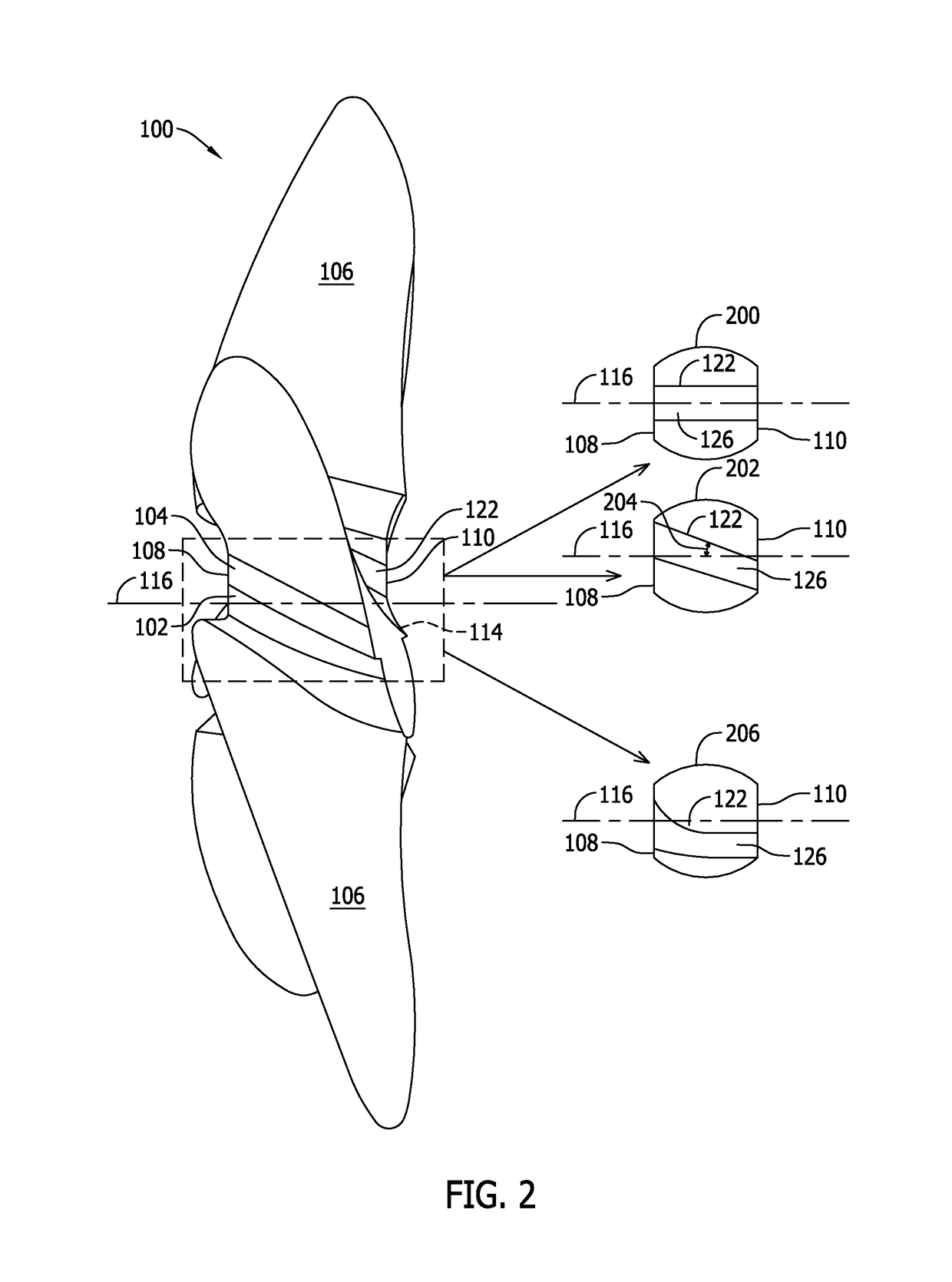
BACKGROUND[0001]The field of the disclosure relates generally to propulsion systems and, more particularly, to a composite marine propeller and propeller assembly.[0002]At least some known marine propulsion systems rely on a rotating propeller assembly including a central hub and propeller blades extending from the central hub to generate a propulsive force. During operation, the propeller blades become loaded due to the force of fluid flow over the propeller blades. Under certain conditions, such loading may be sufficient to cause bending or other deformation of the propeller blade. Bending may induce localized stress within the propeller blades. For example, stress may be induced due to areas of the propeller blade impinging upon other structures, such as the central hub. Such stress can result in premature failure of the propeller blades or may require the propeller blades to be heavier and more robust, thereby requiring a more powerful drive and decreasing the efficiency of the ...

Claims


Application Information

Patent Timeline
IPC IPC(8): F01D5/30B63H1/20
CPCB63H1/20B63B2748/00F01D5/30F05D2260/941Y02T50/60
Inventor KRAY, NICHOLAS JOSEPHVAN NIEUWENHOVE, STEFAAN GUIDOBAEHMANN, PEGGY LYNN
Owner GENERAL ELECTRIC CO
Learn More