Luminescence measuring device
a technology of luminescence measurement and measuring device, which is applied in the field of luminescence detection to achieve the effects of suppressing noise, high bioluminescence measurement, and suppressing temperature-derived variations in background signal
- Summary
- Abstract
- Description
- Claims
- Application Information
AI Technical Summary
Benefits of technology
Problems solved by technology
Method used
Image


Examples
embodiment 1
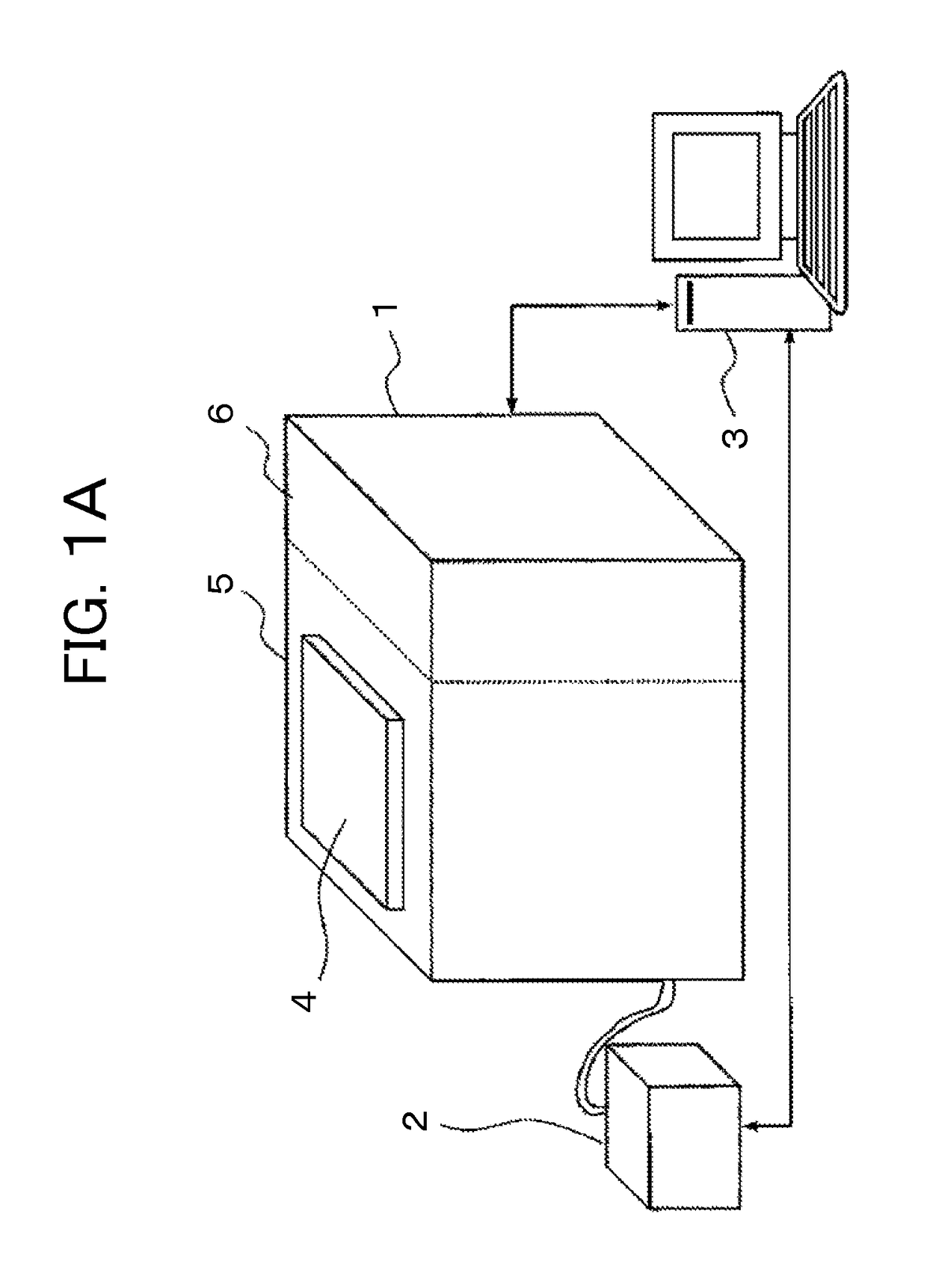
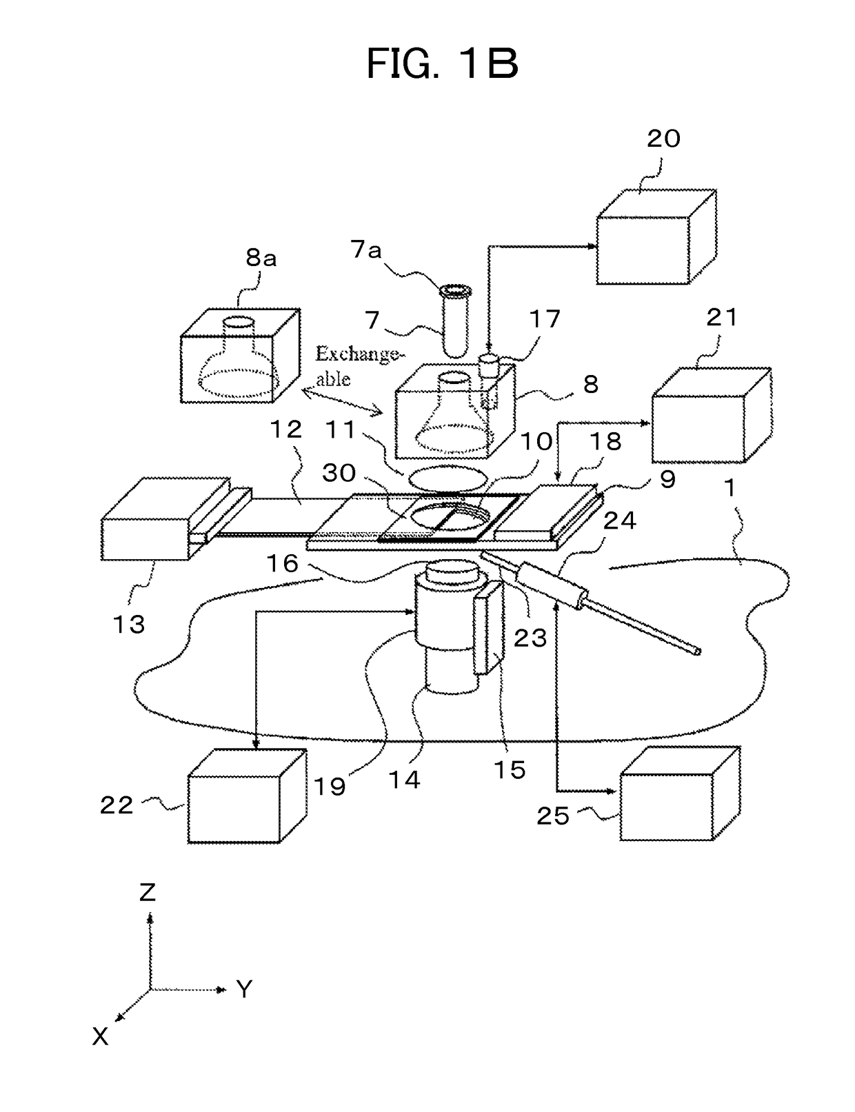
[0039]FIG. 1A, FIG. 1B, FIG. 1C are examples showing a configuration in a measuring room 5 of a weak luminescence measuring device pertaining to the embodiment 1. FIG. 1A is an outside view of a system configured by a weak luminescence measuring device main body 1, a compressor 2 that generates compressed air and a control device 3 that controls it. FIG. 1A, the weak luminescence measuring device main body 1 is a light shielded housing and is further configured by the measuring room 5 that has contained various drive mechanical components and a control room 6 that has contained various control devices. It is provided with an open / close door 4 that opens and closes when setting a sample container 7 shown in FIG. 1B. The device configuration of the inside thereof is as shown in FIG. 1B, FIG. 1C.
[0040]FIG. 1B shows an exploded diagram and FIG. 1C shows a sectional diagram of the assembled one. The sample container 7 is set into a sample container holder 8. The sample container holder 8...
embodiment 2
[0068]It is preferable to use electronic cooling elements (Peltier elements) in the second constant temperature controller 18, the third constant temperature controller 19, the fourth constant temperature controller 24 in order to set the set temperatures of the second constant temperature controller 18, the third constant temperature controller 19, the fourth constant temperature controller 24 to not more than 10° C. FIG. 2A shows a configuration diagram of the second constant temperature controller 18 of the first plate member 9 when a first electronic cooling element has been used. Here, the second constant temperature controller 18 is configured by a cooling surface 31 of the electronic cooling element, a heat radiating surface 33 of the first electronic cooling element, a first heat discharger 34, a first cooling medium introduction port 35, a first cooling medium discharge port 36 that will be described in the following by using FIG. 2A.
[0069]As shown in FIG. 2A, in the electr...
embodiment 3
[0081]FIG. 3B and FIG. 3C show modified embodiments of a temperature adjusting method for the constant temperature dry air 26. Unlike FIG. 3A, they are forms not using the constant temperature dry air nozzle 23.
[0082]FIG. 3B is a method of forming a first blast flow path 52 in the first plate member 9, letting dry air flow into the first plate member 9 that has been temperature-adjusted by the second constant temperature controller 18 so as to adjust it to the same temperature as that of the first plate member 9, and letting the constant temperature dry air 26 flow in parallel with the light receiving surface 16. That is, the air that has been supplied from the compressor 2 passes through the second filter 29, the first filter 28, the air dryer 27 and thereafter this dry air is temperature-adjusted by passing through the blast flow path 52 in the first plate member 9 and is sent in parallel with the light receiving surface 16. Since temperature adjustment of the constant temperature...
PUM
| Property | Measurement | Unit |
|---|---|---|
| wavelengths | aaaaa | aaaaa |
| wavelengths | aaaaa | aaaaa |
| transmittance | aaaaa | aaaaa |
Abstract
Description
Claims
Application Information
 - R&D
- Intellectual Property
- Life Sciences
- Materials
- Tech Scout
- Unparalleled Data Quality
- Higher Quality Content
- 60% Fewer Hallucinations
Browse by: Latest US Patents, China's latest patents, Technical Efficacy Thesaurus, Application Domain, Technology Topic, Popular Technical Reports.
© 2025 PatSnap. All rights reserved.Legal|Privacy policy|Modern Slavery Act Transparency Statement|Sitemap|About US| Contact US: help@patsnap.com