Automatic drain for fuel processor

a technology of automatic draining and fuel processor, which is applied in the direction of filtration separation, separation processes, instruments, etc., can solve the problems of needing ongoing maintenan

Active Publication Date: 2017-06-20
DAVCO TECH
View PDF32 Cites 67 Cited by
  • Summary
  • Abstract
  • Description
  • Claims
  • Application Information

AI Technical Summary

Benefits of technology

[0004]One aspect of the disclosed embodiments is an automatic water drain apparatus that includes a reservoir, a fluid inlet that is in fluid communication with the reservoir, and a first valve member that is moveable between an open position for admitting fluid to the reservoir via the fluid inlet and a closed position for preventing admission of fluid to the reservoir via the fluid inlet. The apparatus also includes a fluid outlet that is in fluid communication with the reservoir, and a second valve member that is moveable between an open position for exhausting fluid from the reservoir and a closed position for preventing exhaust of fluid from the reservoir. The apparatus includes at least one actuator that is operable to move the fluid inlet and the fluid outlet between their respective open and closed positions. A sensor is disposed outside the reservoir and is operable to produce a first sensor output signal in response to detection of the presence of water. The at least one actuator moves the first valve to the open position in response to the first sensor output signal.
[0005]Another aspect of the disclosed embodiments is an automatic drain assembly including a container having water disposed within an interior of the container, a reservoir, a fluid inlet that is in fluid communication with the reservoir and the interior of the container, and a first valve member that is moveable between an open position for admitting water from the container to the reservoir via the fluid inlet and a closed position for preventing admission of water to the reservoir from the container via the fluid inlet. The apparatus also includes a fluid outlet that is in fluid communication with the reservoir, and a second valve member that is moveable between an open position for exhausting fluid from the reservoir and a closed position for preventing exhaust of fluid from the reservoir. The apparatus also includes at least one actuator that is operable to move the fluid inlet and the fluid outlet between their respective open and closed positions. The apparatus further includes a sensor that is disposed in the interior of the container and is operable to generate a first sensor output signal in response to a high water level in the container and a second sensor output signal in response to a low water level in the container. The first sensor output signal causes the at least one actuator to move the first valve member to the open position and the second sensor output signal causes the at least one actuator to move the first valve member to the closed position.
[0006]Another aspect of the disclosed embodiments is an automatic drain assembly includes a container having a volume of water and a volume of fuel disposed within an interior of the container, a housing that is connected to the container, a reservoir disposed within the housing, a fluid inlet that is defined by the housing and is positioned adjacent to a top surface of the housing, wherein the fluid inlet is in fluid communication with the reservoir and the interior of the container, and a first valve member that is moveable between an open position for admitting water from the container to the reservoir via the fluid inlet and a closed position for preventing admission of water to the reservoir from the container via the fluid inlet. The apparatus also includes a fluid outlet that is defined by the housing and is positioned adjacent to a bottom surface of the housing, wherein the fluid outlet is in fluid communication with the reservoir, and a second valve member that is moveable between an open position for exhausting fluid from the reservoir and a closed position for preventing exhaust of fluid from the reservoir. The apparatus also includes at least one actuator that is operable to move the fluid inlet and the fluid outlet between their respective open and closed positions, and a sensor that is disposed in the interior of the container and is operable to generate a first sensor output signal in response to a high water level in the container and a second sensor output signal in response to a low water level in the container. The first sensor output signal causes the at least one actuator to move the first valve member to the open position and the second sensor output signal causes the at least one actuator to move the first valve member to the closed position.

Problems solved by technology

Some designs utilize manual drains, but this creates a need for ongoing maintenance.

Method used


Image

  • Automatic drain for fuel processor
  • Automatic drain for fuel processor
  • Automatic drain for fuel processor

Examples


Embodiment Construction

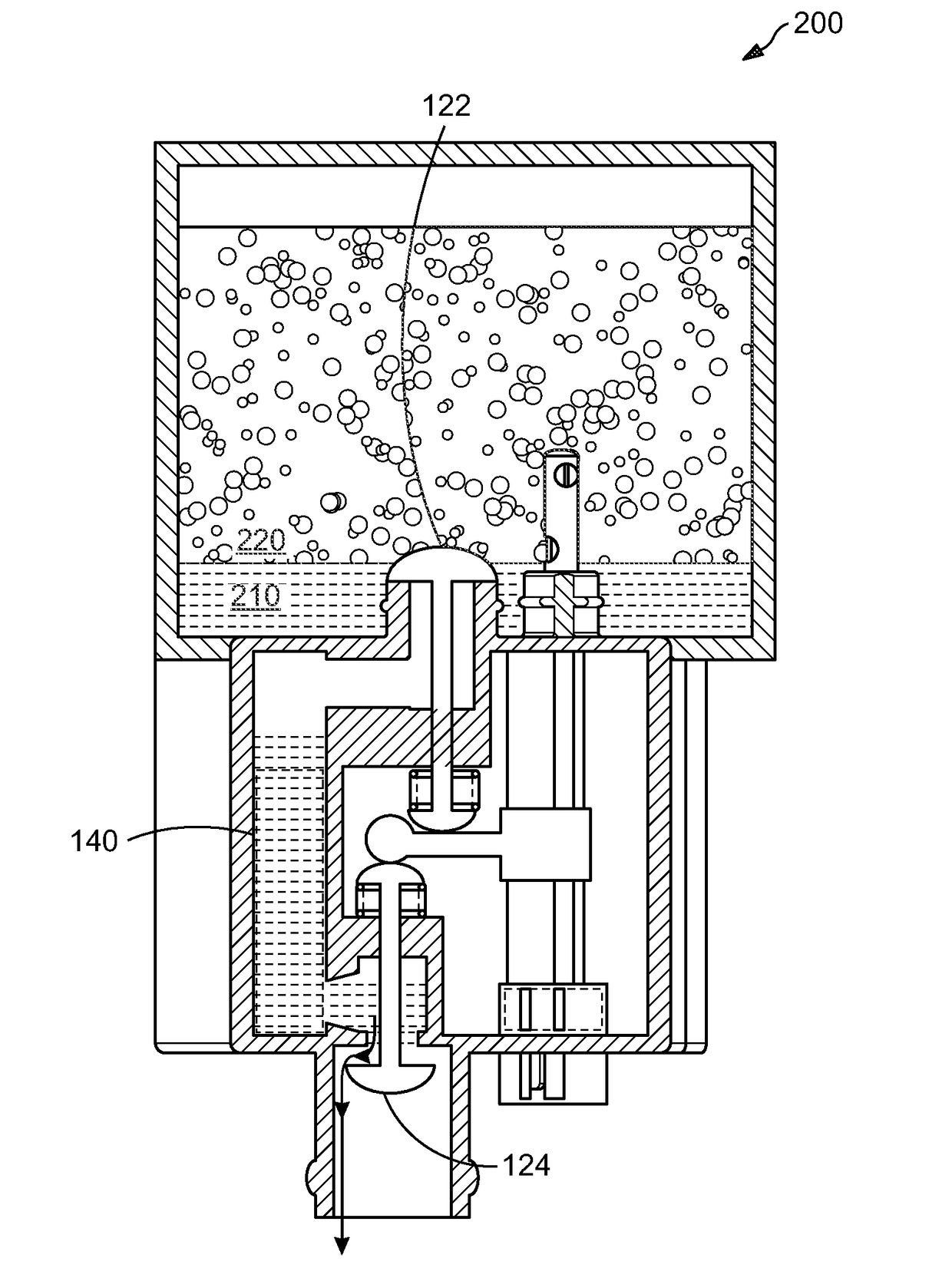
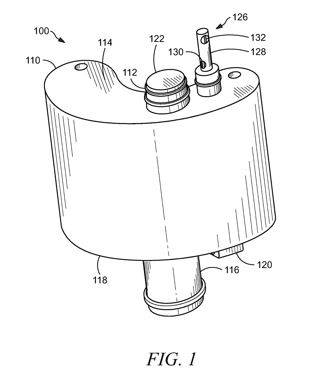
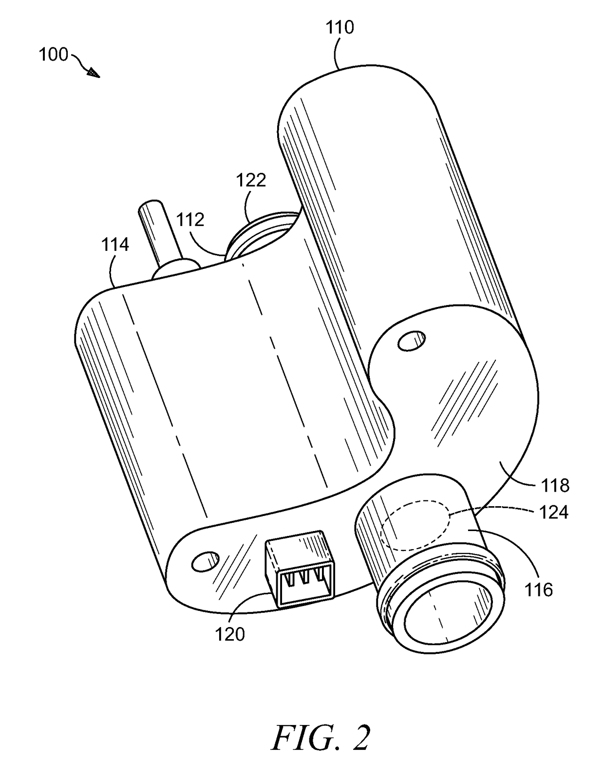
[0013]The disclosure herein relates to an automatic water drain apparatus for fuel processors, such as diesel fuel filter assemblies. The automatic water drain apparatus is installed in communication with a container in which water separates from fuel by collecting at the bottom of the container. A sensor is utilized by the automatic water drain apparatus to open a first valve that causes water from the container to flow into a reservoir within the automatic water drain apparatus. The sensor closes the first valve prior to the point at which the water level within the container would become low enough that fuel might enter the reservoir of the automatic water drain apparatus. When the first valve is closed, a second valve is opened, and the second valve allows the water within the reservoir to pass out of the automatic water drain apparatus while the reservoir is blocked from fluid communication with the container. A filter can be installed within the reservoir for removing impuriti...


PUM

PropertyMeasurementUnit
volumeaaaaaaaaaa
areaaaaaaaaaaa
electrical poweraaaaaaaaaa

Abstract

An automatic water drain apparatus includes a reservoir, a fluid inlet, and a fluid outlet. A first valve member is moveable between an open position for admitting fluid to the reservoir via the fluid inlet and a closed position for preventing admission of fluid to the reservoir. A second valve member is moveable between an open position for exhausting fluid from the reservoir and a closed position for preventing exhaust of fluid from the reservoir. At least one actuator is operable to move the fluid inlet and the fluid outlet between their respective open and closed positions. A sensor is disposed outside the reservoir and is operable to produce a first sensor output signal in response to detection of the presence of water, wherein the at least one actuator moves the first valve to the open position in response to the first sensor output signal.

Description

CROSS-REFERENCE TO RELATED APPLICATIONS[0001]This application claims the benefit of U.S. Provisional Application Ser. No. 61 / 791,382, filed on Mar. 15, 2013, which is incorporated herein in its entirety by reference.TECHNICAL FIELD[0002]This disclosure relates to the field of separating water from fuel.BACKGROUND[0003]In some fuel processing applications, water is mixed into the fuel and needs to be separated from the fuel before the fuel is utilized. One example arises in the context of a diesel fuel processor for a diesel internal combustion engine. The diesel fuel processor may include a housing with a filter media therein for removing particulate contaminants from the diesel fuel. In some previous designs of diesel fuel processors, a reservoir is provided below the area where the diesel fuel passes through the filter media. Because water is heavier than fuel, water will tend to separate from the fuel and collect in the bottom of the reservoir. Occasionally, the reservoir will ne...

Claims


Application Information

Patent Timeline
Patent Type & Authority Patents(United States)
IPC IPC(8): B01D3/42G05D9/12F02M37/22B01D36/00F02M37/28F02M37/32
CPCG05D9/12B01D36/006F02M37/221Y10T137/7313F02M37/28F02M37/32F02M37/24
Inventor CHAJEC, ZDZISLAW W.
Owner DAVCO TECH
Why Eureka
Try Eureka