Wrench

a wrench and wrench technology, applied in the field of wrenches, to achieve the effect of quick tightening of bolts

Active Publication Date: 2017-06-27
HANGZHOU GREAT STAR TOOLS +1
View PDF24 Cites 2 Cited by
  • Summary
  • Abstract
  • Description
  • Claims
  • Application Information

AI Technical Summary

Benefits of technology

[0012]In another preferred embodiment of the present invention, the planetary gear speed increasing mechanism increases the rotation speed inputted by the gear ring by four times and the rotation is output through the main axle.
[0013]When the wrench according to the present invention is in use, the outputted torque required by the wrench is small, users do not need to rotate the handle at this time but simply hold the handle and rotate the rotation ring by hands when tightening bolts at the initial stage under conditions of low torque output, the main axle will be rotated with higher speed than the rotation speed of the rotation ring, the rotation direction is the same as the rotation direction of the rotation ring, thus bolts can be tightened quickly; the outputted torque required by the wrench is large, users can preset the output direction of the main axle of wrench by rotating knob when tightening bolts on the final stage under conditions of high torque output, such as clockwise or counterclockwise. At this time if users rotate the handle in the set output direction, the main axle will be rotated in the direction at the same speed; if users rotate the handle in the opposite direction of the set output direction, the main axle remains stationary at this point.

Problems solved by technology

Sometimes the rotation in the opposite direction is achieved by releasing the hand gripping the handle with the help of the other hand, and such operation is very inconvenient.

Method used


Image

  • Wrench
  • Wrench
  • Wrench

Examples


Embodiment Construction

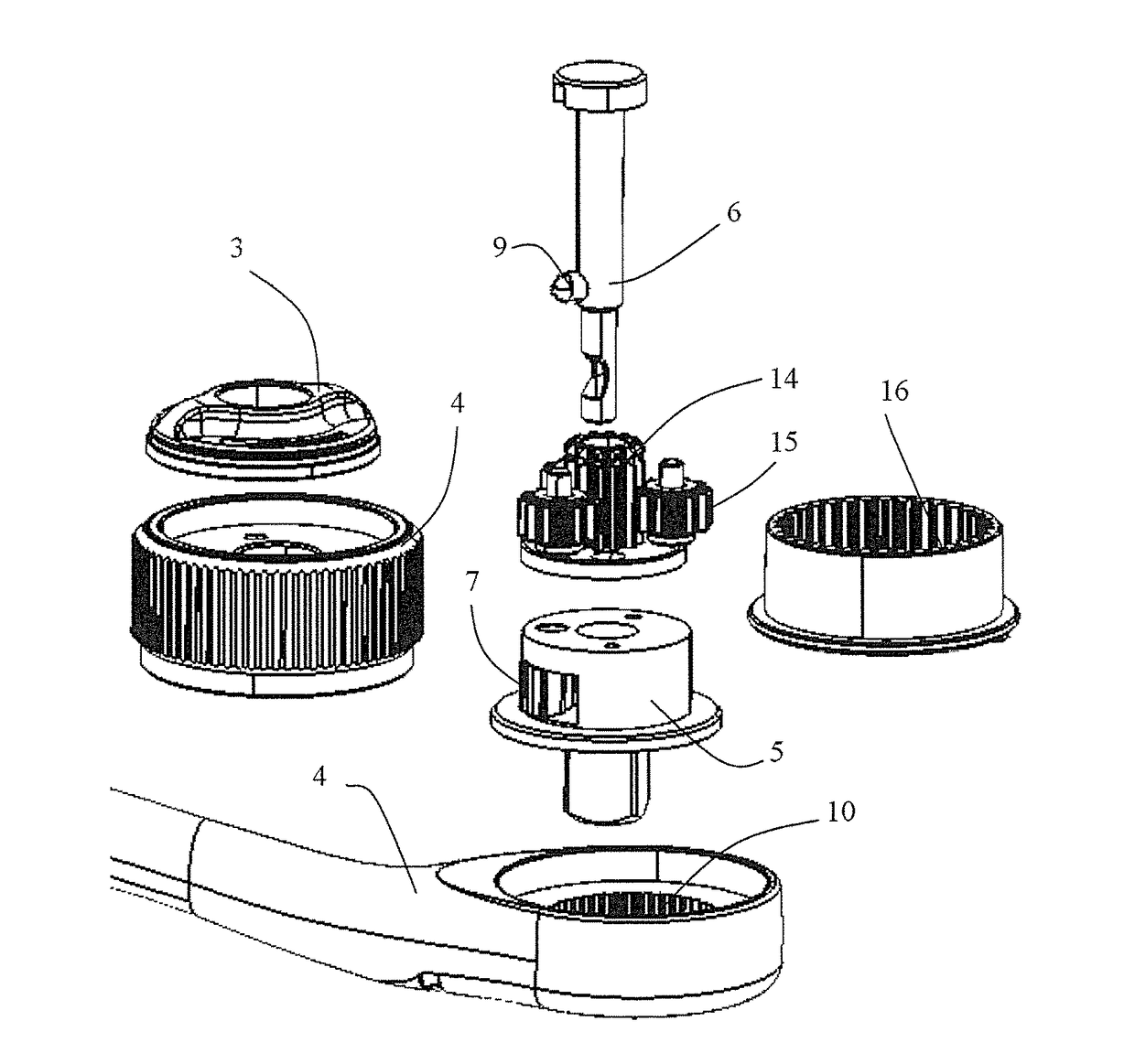
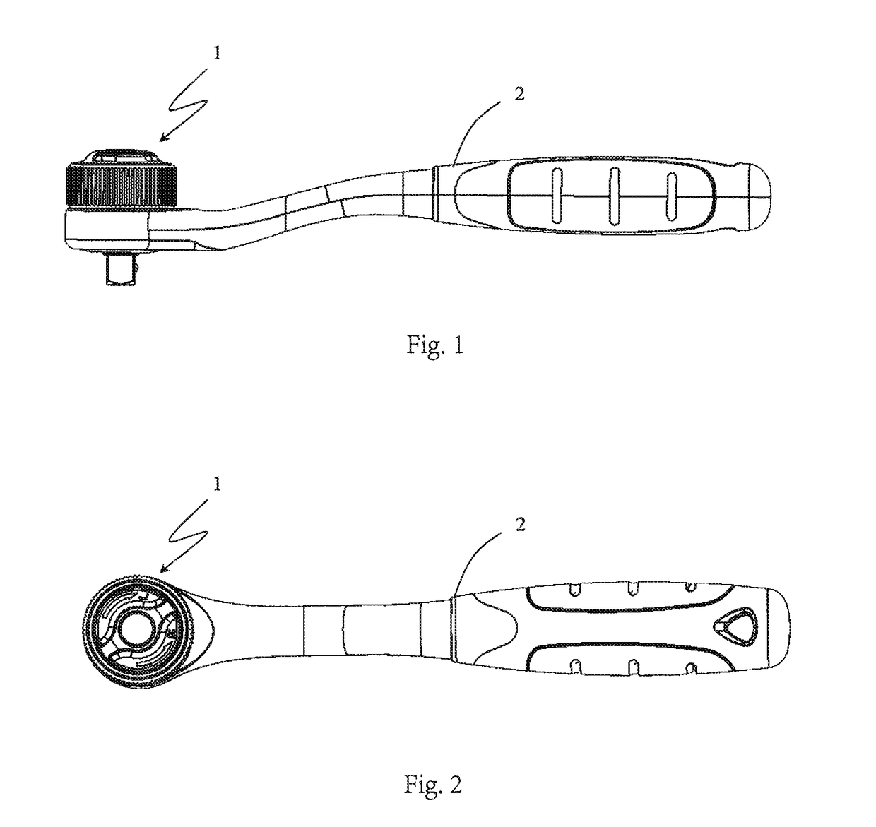
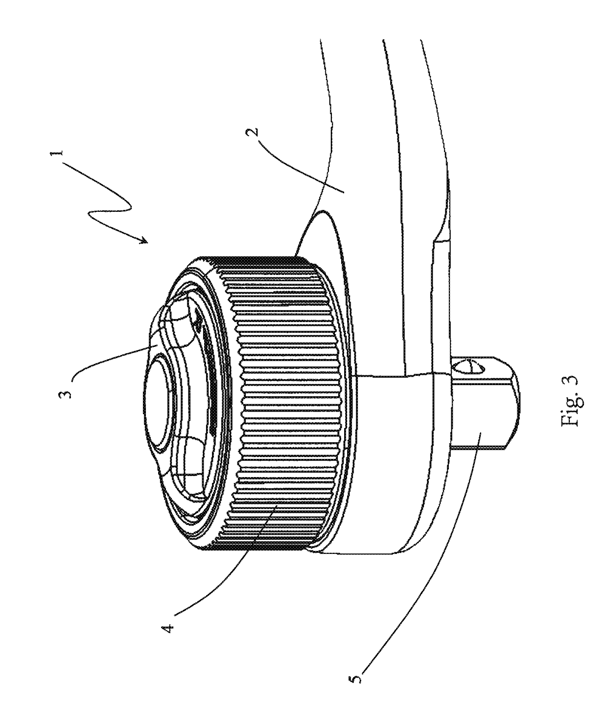
[0027]FIG. 1, 2 show a front view and a top view of a wrench according to a preferred embodiment of the present invention, it can be seen that the wrench comprises a working part 1 and a handle 2, wherein the axis of the working part 1 is perpendicular to the handle 2. As shown in FIG. 3, the working part 1 has a knob 3, a rotating ring 4, an annular handle 2 sheathing outside of the working part 1, and a main axle 5 extending out from the working part 1 in the axial direction of the working part 1 in the present embodiment. The outputted torque required by the wrench is small, users do not need to rotate the handle at this time, by simply holding the handle 2 and rotate the rotation ring 4 by hands when tightening bolts at the initial stage under conditions of low torque output, the main axle 5 will be rotated with higher speed than the rotation speed of the rotation ring 4, the rotation direction is the same as the rotation direction of the rotation ring 4, thus bolts can be tight...


PUM


Abstract

The present invention provides a wrench, which comprises a working part and a handle, the working part includes a main axle perpendicular to the handle and mutually cooperated bidirectional pawl and ratchet wheel, in which the ratchet wheel is arranged so as to be caused by the handle, the bidirectional pawl is arranged to rotate the main axle and has a first pawl and a second pawl which are opposite to the clutch direction between the ratchet wheel, the working part also includes a direction switching mechanism for setting clutch direction of the bidirectional pawl and the ratchet wheel; the direction switching mechanism is arranged such that a first pawl and a second pawl are engaged with the ratchet wheel selectively, such that when handle is rotated in the direction set by the direction switching mechanism, the ratchet wheel is engaged with the bidirectional pawl, then rotates the main axle; when the handle is rotated in the direction opposite to the direction set by the direction switching mechanism, the ratchet wheel and the bidirectional pawl slide over each other, and the main axle remains stationary; the working part also includes a planetary gear speed increasing mechanism acting on the main axle, the planetary gear speed increasing mechanism includes a sun gear, a planetary gear and a ring gear, in which the sun gear is arranged to rotate the main axle together, the rotation ring is arranged so as to cause the planetary gear to rotate, the gear ring is fixedly connected with the handle, so that when the handle is gripped and the rotation ring is rotated, the planetary gear speed increasing mechanism increases the speed of the rotation inputted by the rotation ring and then outputs via the main axle.

Description

FIELD OF THE INVENTION[0001]The present invention relates to a wrench, and pertains to the field of hand tools.DESCRIPTION OF THE PRIOR ART[0002]When using an ordinary wrench, due to the hand gripping the handle can only rotate a small angle, so that when one needs to consecutively rotate one component for multiple times, a halt is needed to allow the hand to rotate an angle in the opposite direction. Sometimes the wrench is taken away temporarily from the component to allow rotation in the opposite direction. In this way the operator needs to align the wrench to the component again. Sometimes the rotation in the opposite direction is achieved by releasing the hand gripping the handle with the help of the other hand, and such operation is very inconvenient.[0003]In addition, when under low torque output conditions, the working efficiency of the wrench is significantly improved if the component can be rotated as soon as possible.[0004]Therefore, the person skilled in the art is commi...

Claims


Application Information

Patent Timeline
Patent Type & Authority Patents(United States)
IPC IPC(8): B25B13/46B25B17/00
CPCB25B13/467B25B13/465B25B17/00
Inventor WANG, MIN
Owner HANGZHOU GREAT STAR TOOLS
Why Eureka
Try Eureka