Cranking-caused vibration suppressing apparatus and method for internal combustion engine

a technology of internal combustion engine and apparatus, which is applied in the direction of engine starters, electric control, machines/engines, etc., can solve the problems of small output torque and great output torque of motors, and achieve the suppression of engine vibrations, small output torque, and great output torque

Inactive Publication Date: 2008-01-01
TOYOTA JIDOSHA KK
View PDF18 Cites 2 Cited by
  • Summary
  • Abstract
  • Description
  • Claims
  • Application Information

AI Technical Summary

Benefits of technology

[0008]Accordingly, it is one object of the invention to provide a cranking-caused vibration suppressing apparatus and method for an internal combustion engine that copes with the problem of vibrations occurring during the cranking of the engine, which is expected to greatly affect the riding comfort and the noise suppression of a vehicle in terms of timing and rate of occurrence of the vibrations.
[0011]In the vibration suppressing apparatus and method described above, the operation of the motor is controlled on the basis of the detected crankshaft rotational phase so that the output torque of the motor fluctuates similarly to a fluctuation in the resistance torque against the cranking of the engine presented by the crankshaft in accordance with the rotational phase thereof, the fluctuation in the resistance torque including at least the fluctuation in the resistance torque caused by intake air compression. Therefore, the motor produces an output torque corresponding to fluctuations in the resistance torque occurring on the crankshaft of the internal combustion engine. That is, the motor produces great output torque when the resistance torque is great, and produces small output torque when the resistance torque is small. As a result, vibrations of the engine are suppressed at the time of the cranking of the engine. Hence, the invention improves the riding comfort and the noise suppression during the engine cranking in a vehicle equipped with the above-described engine.

Problems solved by technology

That is, the motor produces great output torque when the resistance torque is great, and produces small output torque when the resistance torque is small.

Method used


Image

  • Cranking-caused vibration suppressing apparatus and method for internal combustion engine
  • Cranking-caused vibration suppressing apparatus and method for internal combustion engine
  • Cranking-caused vibration suppressing apparatus and method for internal combustion engine

Examples


Embodiment Construction

[0019]In the following description and the accompanying drawings, the present invention will be described in more detail in terms of exemplary preferred embodiments.

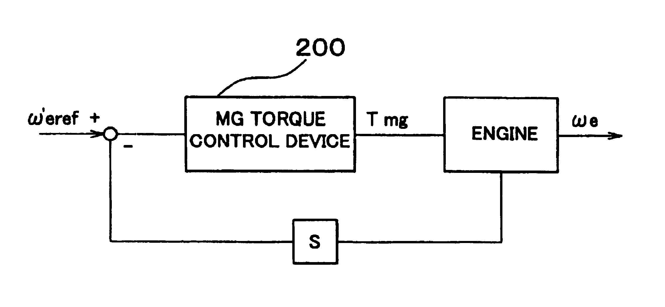
[0020]FIG. 2 is a diagram illustrating a power system of a hybrid vehicle to which a vibration suppressing apparatus in accordance with the invention is applied. A reciprocating piston engine 10, that is, a type of internal combustion engine, drives wheels (not shown) via an output shaft of the engine 10, and also drives an air conditioner 20, a power steering pump (PS pump) 30 and a water pump 50, via an endless belt 80 that is disposed and turned around the output shaft of the engine 10, the air conditioner 20, the power steering pump 30, a tensioner 40, the water pump 50, a motor-generator (MG) 60 and an idler 70. When a battery device (not shown) is to be charged, the motor-generator 60 is operated as a generator. The motor-generator 60 also may operate as an electric motor. When the engine 10 is to be started, the m...


PUM


Abstract

At the time of (i.e., during) cranking of an internal combustion engine, an engine cranking-caused vibration suppressing apparatus and method controls the operation of an electric motor that cranks the internal combustion engine based on the rotational phase of the crankshaft detected by a crankshaft rotational phase detector so that the output torque of the motor fluctuates similarly to fluctuations in resistance torque against the cranking of the engine that the crankshaft presents in accordance with the rotational phase thereof. Thus, the apparatus and method are able to suppress vibrations during the cranking of the engine, leading to improvements in the riding comfort and the noise suppression of a vehicle.

Description

INCORPORATION BY REFERENCE[0001]The disclosure of Japanese Patent Application No. 2000-358905 filed on Nov. 27, 2000, including the specification, drawings and abstract is incorporated herein by reference in its entirety.BACKGROUND OF THE INVENTION[0002]1. Field of Invention[0003]The invention relates to apparatus and methods for suppressing vibrations of an internal combustion engine caused by the cranking of the engine.[0004]2. Description of Related Art[0005]A reciprocating piston engine, that is, a type of internal combustion engine, is started by a cranking operation of turning a crankshaft of the engine via an electric motor. Conventionally, substantially no technical attention has been given to vibrations caused at the time of the cranking of the engine, more precisely, during the cranking thereof. With regard to the vibrations at the time of a start of an engine, Japanese Patent Application Laid-Open No. 10-212983 describes an arrangement in which an engine is cranked by a f...

Claims


Application Information

Patent Timeline
Patent Type & Authority Patents(United States)
IPC IPC(8): F02N11/00F02B77/00B60W10/08B60W20/00F02B77/08F02D29/02F02D41/14F02N11/04F02N11/08
CPCB60W10/08B60W30/20F02B67/06F02D41/1498F02D2200/1012F02D2200/1015F02D2250/18F02D2250/21F02N11/08F02N11/0814F02N2200/021F02N2200/022F02N2300/104
Inventor SUZUKI, TAKASHI
Owner TOYOTA JIDOSHA KK
Why Eureka
Try Eureka