
Connecting device with a clamping device for connecting to an arrangement for closing flow paths and monitoring the status of the clamping device and method for same

a technology of a clamping device and a connection device, which is applied in the direction of diaphragm valves, engine diaphragms, other blood circulation devices, etc., can solve the problems of inability to apply methods to existing arrangements, and inability to easily integrate additional clamping devices or valve devices into existing devices, etc., to achieve rapid, easy and reliable results

Active Publication Date: 2017-07-04
FRESENIUS MEDICAL CARE DEUTSCHLAND GMBH
View PDF12 Cites 0 Cited by
  • Summary
  • Abstract
  • Description
  • Claims
  • Application Information

AI Technical Summary

Benefits of technology

The present invention relates to a connecting device for diagnostic and treatment methods that can be used in various flow schemes. It allows for flexible and universal use of the device through the adaptation of the connecting devices. The main technical effect of the invention is the provision of an affordable and easy-to-use solution for adapting the connecting device to different diagnostic and treatment methods, thereby reducing the cost and complexity of the arrangement. This is achieved by the use of external function devices such as clamping devices or valve devices that can be quickly and reliably adapted to the respective requirements of a method, allowing for the flexible and universal use of the arrangement.

Problems solved by technology

It is a disadvantage that it is impossible to easily integrate additional clamping devices or valve devices into an existing device.
Thus if all the clamping devices or valve devices present on the device side are occupied but additional clamping functions are needed, these methods cannot be applied to the existing arrangements.
Another disadvantage is that the use of such methods can be implemented only through extensive structural and technical revision of the arrangement, which is extremely time-consuming and also expensive.

Method used


Image

  • Connecting device with a clamping device for connecting to an arrangement for closing flow paths and monitoring the status of the clamping device and method for same
  • Connecting device with a clamping device for connecting to an arrangement for closing flow paths and monitoring the status of the clamping device and method for same
  • Connecting device with a clamping device for connecting to an arrangement for closing flow paths and monitoring the status of the clamping device and method for same

Examples


first embodiment

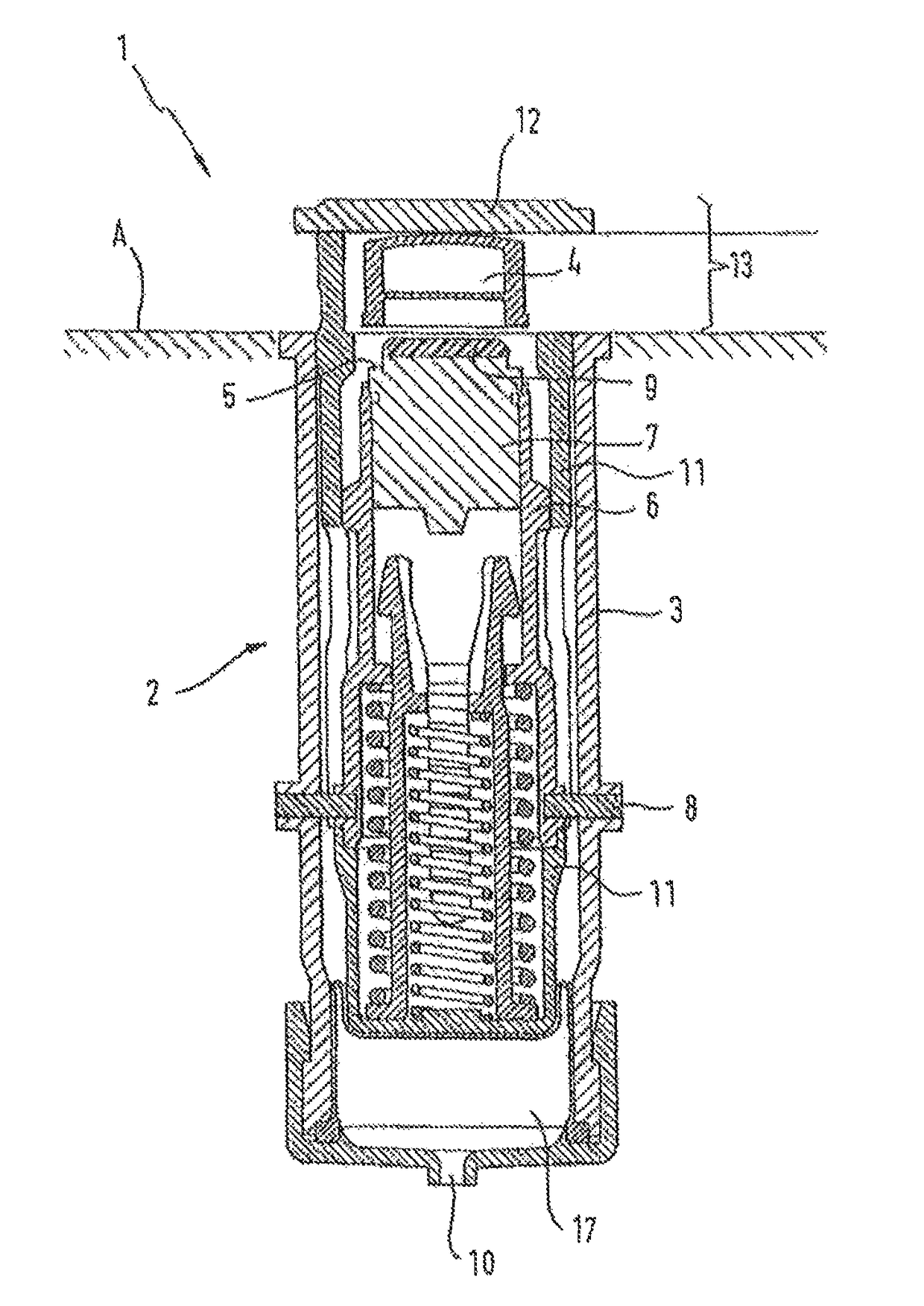
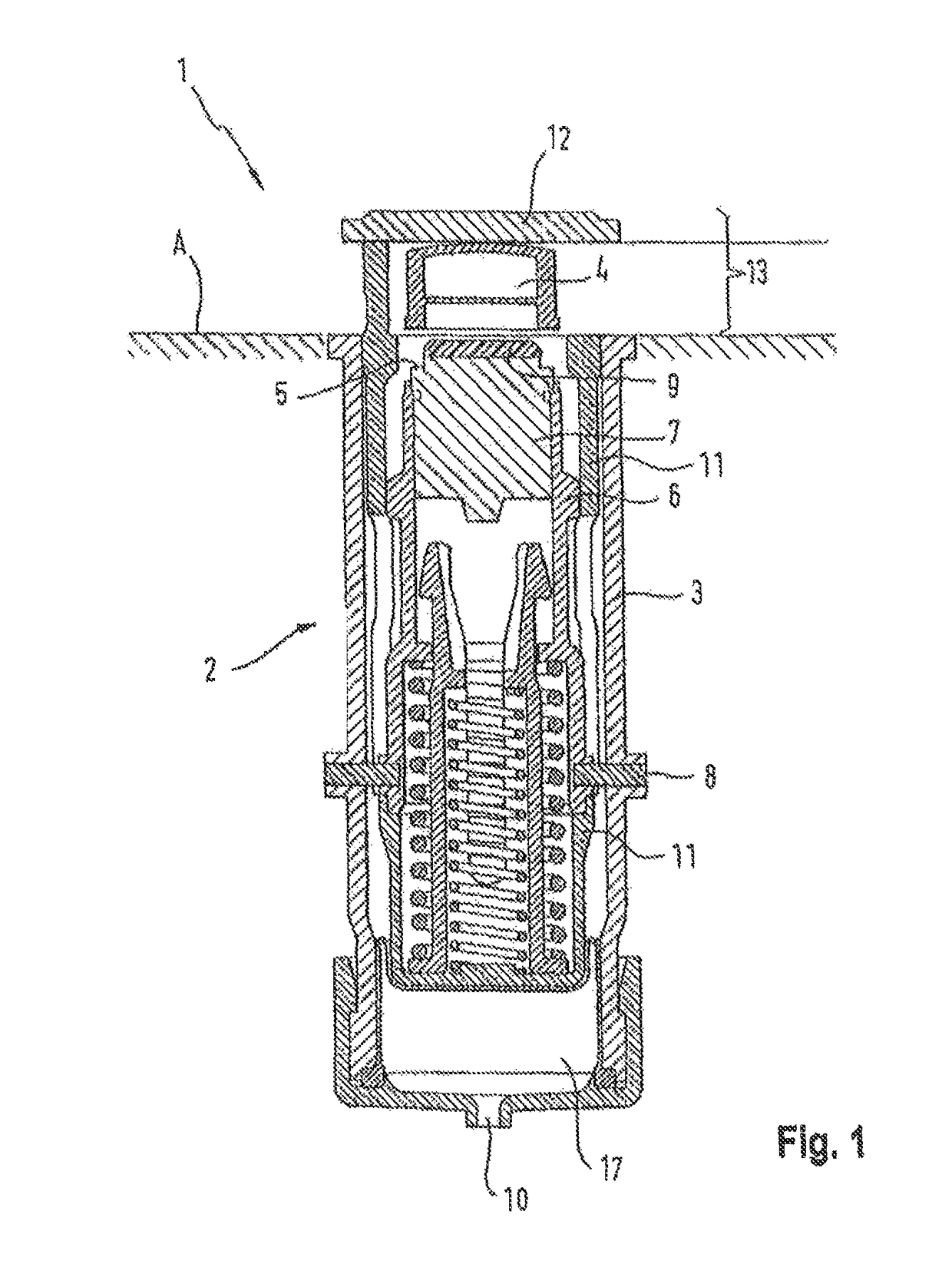
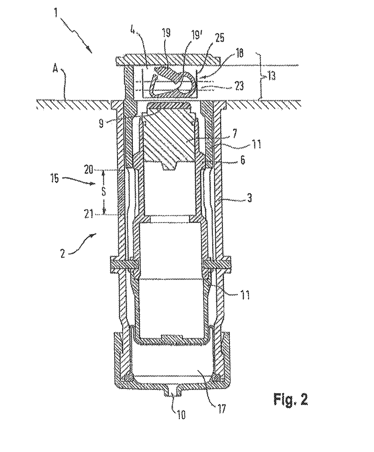
[0062]In the clamping device (18), which is shown in FIG. 3a in the open state, it has a bottom side (24) bordered by a rigid bottom side and / or area, and it has a top side (26). The bottom side in the sense of the invention is the side facing the pressure-measuring unit (7), and the top side is the side facing the pressure plate (12). The top side (26) may be designed as an elastic and / or flexible lever or arm and may act as a clamping element (19). Clamping elements (19) on the bottom and / or top sides (24), (26) may also be designed as inwardly directed clamping prisms, clamping wedges, elevations, arches, mandrels or the like as moulded parts suitable for closing off a fluid-carrying element (23). For the sake of simplicity, only the concept of the clamping prisms (19′) shall be used in the remaining description. The top side (26) may be designed to be open or closed. The clamping device (18) has two opposing side openings which serve as holders (27, 27′) for the fluid-carrying e...

second embodiment

[0081]In a second embodiment as shown schematically in FIG. 6a, the clamping device (18) may have as the fluid carrying element (23) a flow-through chamber (31), which at the same time also represents the housing (25) of the clamping device (18). The flow-through chamber (31) contains a lower side (24), which has sealing contours (32) as clamping elements or clamping prisms (19, 19′). The lower side (24) facing the sealing contours (32) may be sealed by a flexible membrane (33). The upper side (26), which is directed toward the pressure plate (12), is preferably bordered by a rigid wall. The holders (27, 27′) arranged on the sides are advantageously also designed to be rigid and form a flow connection in the form of a tube, a pipe, a channel or the like that can be connected to an arrangement (1) upstream and downstream from the flow-through chamber (31).

[0082]In the open state, the membrane (33) is not in fluid tight contact with the bottom side of the sealing contours (32) so that...


PUM


Abstract

A connecting device for connecting an external function device to an arrangement and for cutting off flow paths by accommodating a clamping device includes a pressure-measuring unit and / or a length-measuring unit configured to detect a clamping force and / or a distance such that it is possible to monitor the status of the clamping device.

Description

CROSS-REFERENCE TO RELATED APPLICATIONS[0001]This application claim benefit to U.S. Provisional Application No. 61 / 760,441, filed Feb. 4, 2013.BACKGROUND OF THE INVENTION[0002]1. Field of Invention[0003]The present invention relates to a connecting device for connecting an external function device having an arrangement for closing flow paths by accommodating clamping device and a pressure-measuring unit and / or a length-measuring unit for detecting a clamping force and / or a distance, thus making it possible to monitor the status of the clamping device.[0004]2. Description of the Prior Art[0005]Connecting devices for connecting an external function device to an arrangement for diagnostic and treatment methods and the like, such as those used in the medical technical field in particular, are known from the prior art. Such connecting devices are used in particular in arrangements for treating blood in extracorporeal blood circulations. The connecting devices are also equipped with vario...

Claims


Application Information

Patent Timeline
Patent Type & Authority Patents(United States)
IPC IPC(8): A61M39/28F16K37/00F16K7/04A61M1/36
CPCF16K37/0091A61M1/367A61M1/3639A61M39/28F16K7/04F16K37/0083A61M2205/14A61M2205/332Y10T137/0318Y10T137/8158Y10T137/8225Y10T137/8326A61M1/3641
Inventor KLEWINGHAUS, JUERGEN
Owner FRESENIUS MEDICAL CARE DEUTSCHLAND GMBH
Learn More