Wall mount component and wire clamp connector thereof

a wall mount and connector technology, applied in the direction of coupling device connection, coupling contact member, coupling device details, etc., can solve the problems of wires being damaged, broken, or cut by the tips of screws, and the wires cannot be securely positioned on the connector, so as to achieve enhanced fixation between the conductive sheet and the connecting board, and the effect of not being damaged easily

Active Publication Date: 2017-07-04
ADVANCED CONNECTEK INC
View PDF9 Cites 0 Cited by
  • Summary
  • Abstract
  • Description
  • Claims
  • Application Information

AI Technical Summary

Benefits of technology

[0014]Based on the above, the wire can be firmly positioned in the wire groove by the clamp piece having a flat surface, so that the wire would not be damaged easily as well as the wire can be in contact with the clamping piece. In addition, because the offset configuration of the engaging pieces of the conductive sheets, when the engaging pieces are respectively positioned with the engaging grooves of the connecting board, the fixation between the conductive sheets and the connecting board can be enhanced. Moreover, the abutting portion of the lock member is positioned in the U-shaped clamping piece, and the head of the abutting portion is in the flexible space of the clamping piece. The abutting portion is free from contacting the contact sheet of the clamping piece. When the contact sheet pushes against the wire, the contact sheet can be deflected flexibly, so that the contact wire can be held in the wire clamp connector. Furthermore, the wire clamp connector may be applied to the wall mount component so as to be mounted on a wall and connected to an electronic product.

Problems solved by technology

However, the area of the tip of the screw is too small to position the wire on the connector properly; namely, when the screw is threaded to lock the wire with the connector, the tip of the screw cannot be aimed at the wire, so that the wire cannot be securely positioned on the connector.
In addition, when screws are applied to position the wires on the connector, the wires might be damaged, broken, or cut by the tips of the screws because of the sharp protrusions or rough surface of the screw's tip.
Consequently, the electrical transmission would be harmed.
Accordingly, how to improve the existing connector becomes an issue.

Method used


Image

  • Wall mount component and wire clamp connector thereof
  • Wall mount component and wire clamp connector thereof
  • Wall mount component and wire clamp connector thereof

Examples


Embodiment Construction

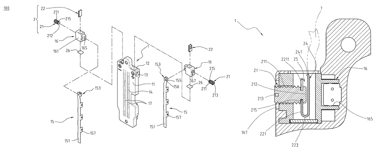
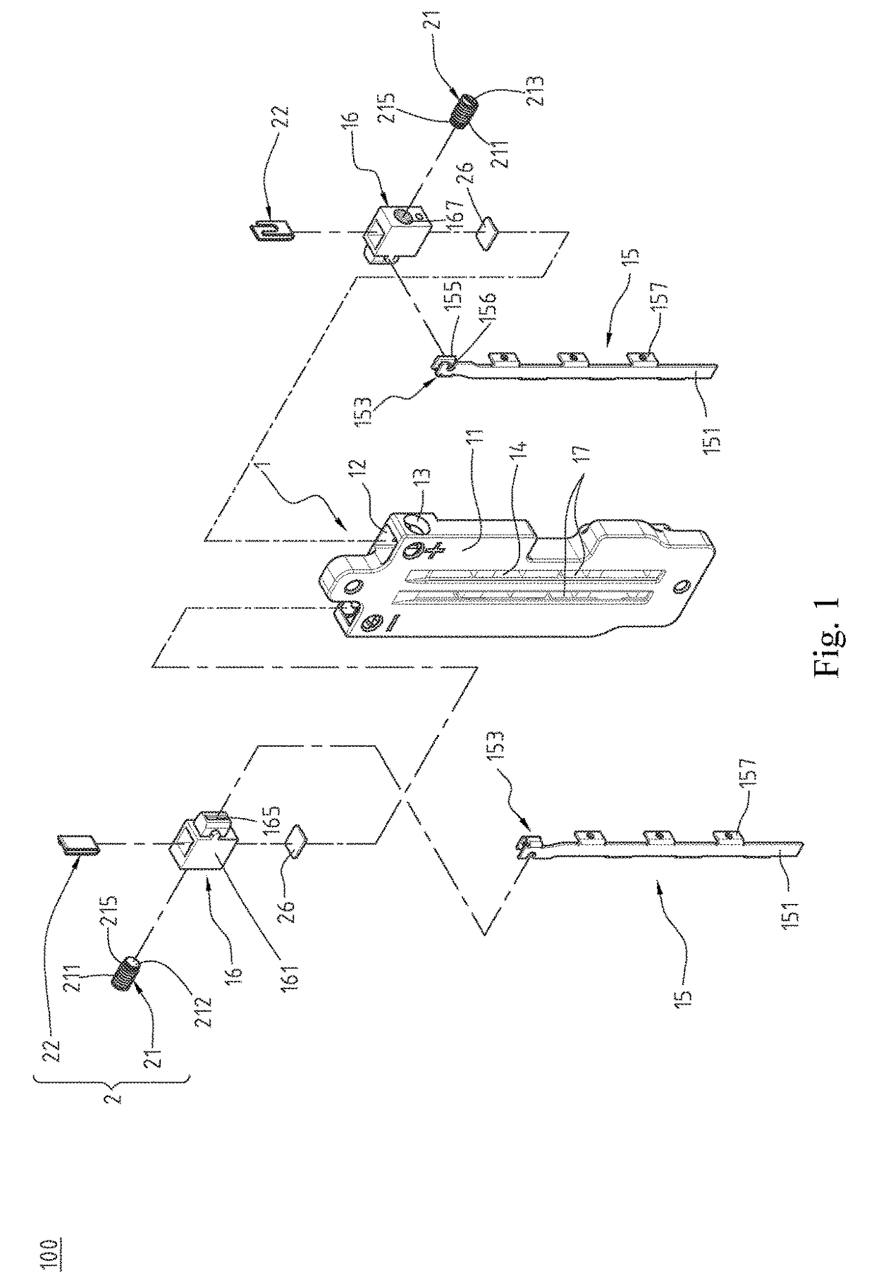
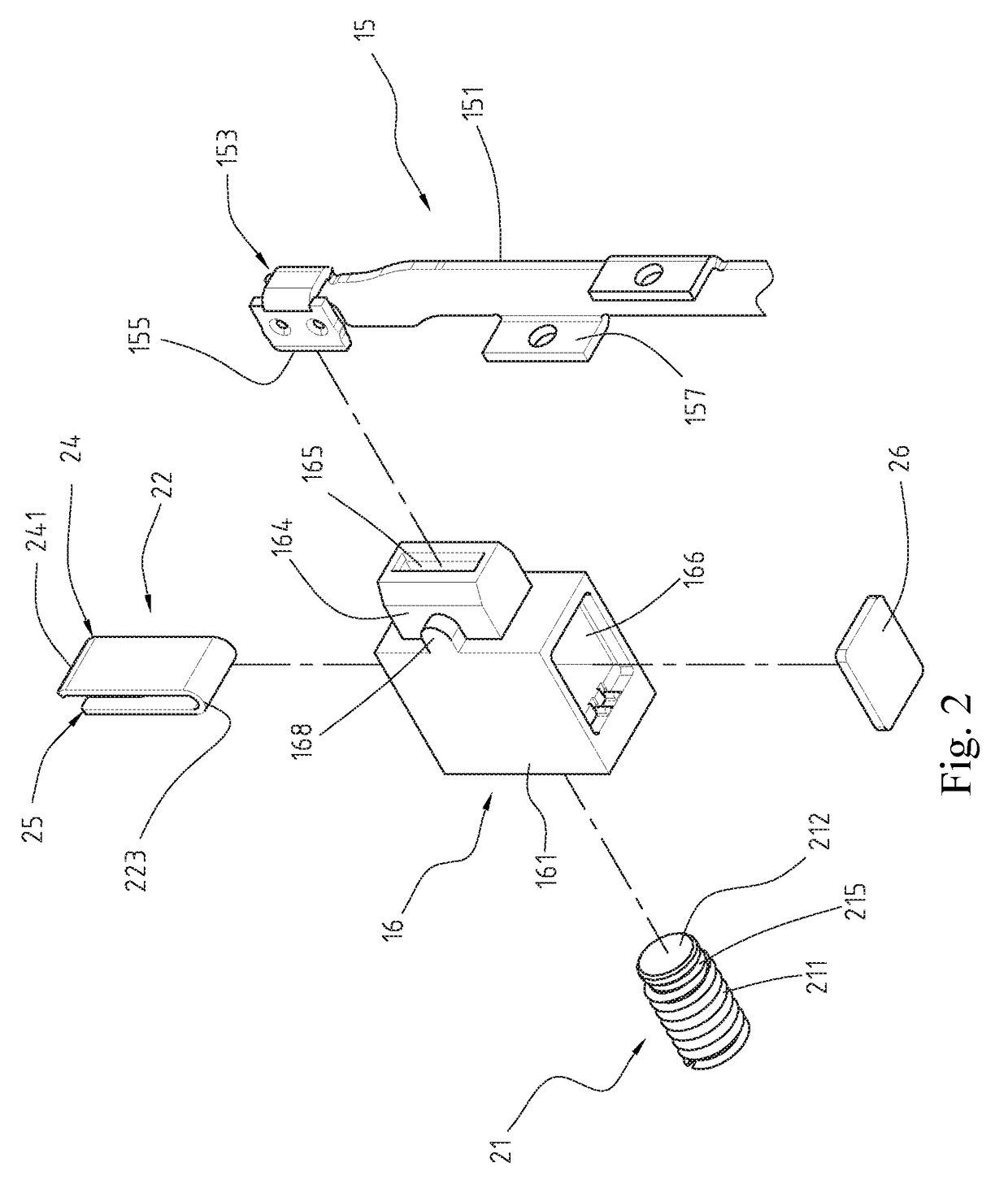
[0025]Please refer to FIGS. 1 to 4, which illustrate a wire clamp connector 100 of a first embodiment of the instant disclosure. FIG. 1 illustrates an exploded view of the wire clamp connector 100. FIG. 2 illustrates a partial exploded view (1) of the wire clamp connector 100. FIG. 3 illustrates a partial exploded view (2) of the wire clamp connector 100. FIG. 4 illustrates a perspective view of the wire clamp connector 100. In this embodiment, the wire clamp connector 100 comprises a connecting board 1, a plurality of conductive sheets 15, a plurality of conductive mounts 16, and a plurality of wire clamp components 2.

[0026]Please refer to FIGS. 1 and 4. The connecting board 1 is an elongate plate made of plastic. The connecting board 1 is insulated and nonconductive. The connecting board 1 comprises a board body 11, a plurality of recessed rails 14, a plurality of assembling holes 12, a plurality of through holes 13, and a plurality of engaging grooves 17. In this embodiment, the ...


PUM


Abstract

A wire clamp connector includes a connecting board, a plurality of conductive sheets, a plurality of conductive mounts, and a plurality of wire clamp components. The conductive sheets are disposed at one surface of the connecting board. The conductive mounts are disposed at the top of the connecting board and connected to the conductive sheets. The wire clamp components are disposed at the respective conductive mounts. Each of the wire clamp components includes a lock member and a clamping piece. The lock member pushes the clamping piece to push against a wire, so that the wire can be firmly positioned with the corresponding conductive mount. Furthermore, the wire clamp connector may be applied to the wall mount component so as to be mounted on a wall and connected to an electronic product.

Description

CROSS-REFERENCES TO RELATED APPLICATIONS[0001]This non-provisional application claims priority under 35 U.S.C. §119(a) on Patent Application No. 201510339268.2 filed in China, P.R.C. on 2015 Jun. 18, the entire contents of which are hereby incorporated by reference.FIELD OF THE INVENTION[0002]The instant disclosure relates to an electrical connector, and more particular to a wall mount component and a wire clamp connector thereof.BACKGROUND[0003]Generally, an electronic device is electrically connected to the main supply, so the electronic device can be driven by the main supply. In other words, the electronic device and the main supply are electrically connected with each other by two mating connectors. A bracket having a connector is fixed on a wall and the connector is connected to the main supply. When the electronic device is placed on the bracket, the connector of the electronic device is electrically connected with the connector of the bracket to receive the electrical power ...

Claims


Application Information

Patent Timeline
Patent Type & Authority Patents(United States)
IPC IPC(8): H01R4/42H01R4/36H01R13/24H01R13/73H01R24/68H01R24/76H01R25/14H01R31/06H01R103/00
CPCH01R4/42H01R4/366H01R13/2421H01R13/73H01R24/68H01R24/76H01R25/145H01R31/06H01R2103/00H01R2201/18H01R4/489
Inventor CHEN, JIN-SHIHOU, PIN-YUAN
Owner ADVANCED CONNECTEK INC
Why Eureka
Try Eureka