Motor and disk drive apparatus

a technology of motor and disk drive, which is applied in the direction of magnetic circuit rotating parts, magnetic circuit shape/form/construction, instruments, etc., can solve the problems of vibration of the spindle motor, and achieve the effect of reducing the degree of roundness

Active Publication Date: 2017-07-04
NIDEC CORP
View PDF11 Cites 1 Cited by
  • Summary
  • Abstract
  • Description
  • Claims
  • Application Information

AI Technical Summary

Benefits of technology

[0008]According to the above preferred embodiment of the present invention, there is no adhesive located between the magnet and a lower axial end portion and a vicinity of the yoke, which are apt to have a reduced degree of roundness. This contributes to preventing the magnet from becoming deformed along a circumferential direction due to a change in a volume of the adhesive at the time of curing thereof.

Problems solved by technology

If a reduction in the degree of roundness of the magnet occurs, a distance between the magnet and a stator becomes uneven along a circumferential direction, causing magnetic forces to be applied unevenly along the circumferential direction, which may cause vibrations of the spindle motor.

Method used


Image

  • Motor and disk drive apparatus
  • Motor and disk drive apparatus
  • Motor and disk drive apparatus

Examples


Embodiment Construction

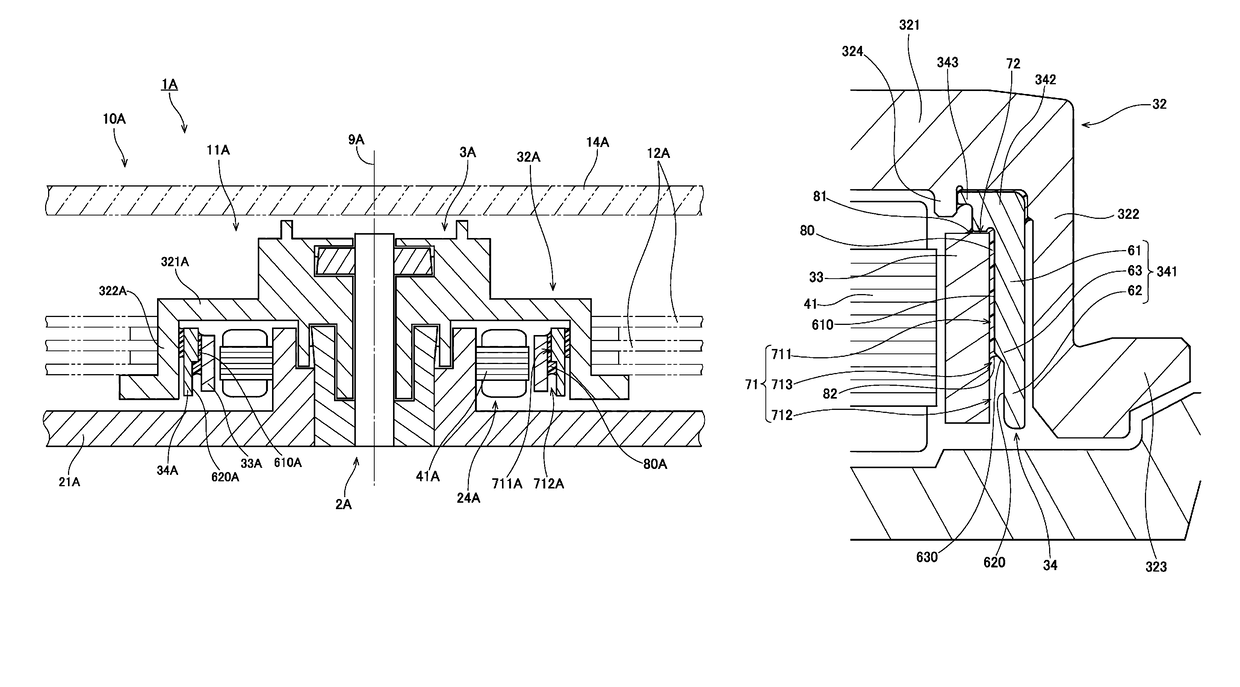
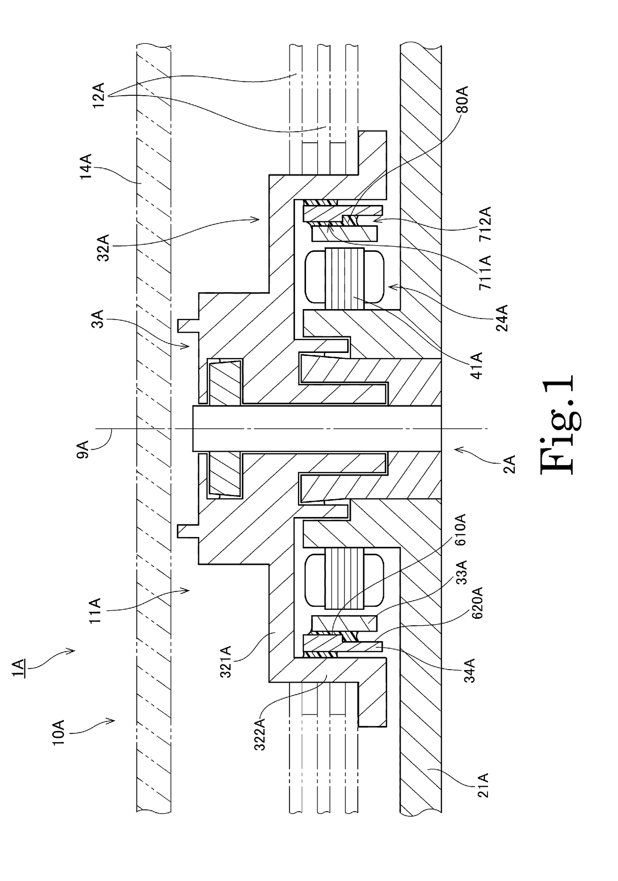
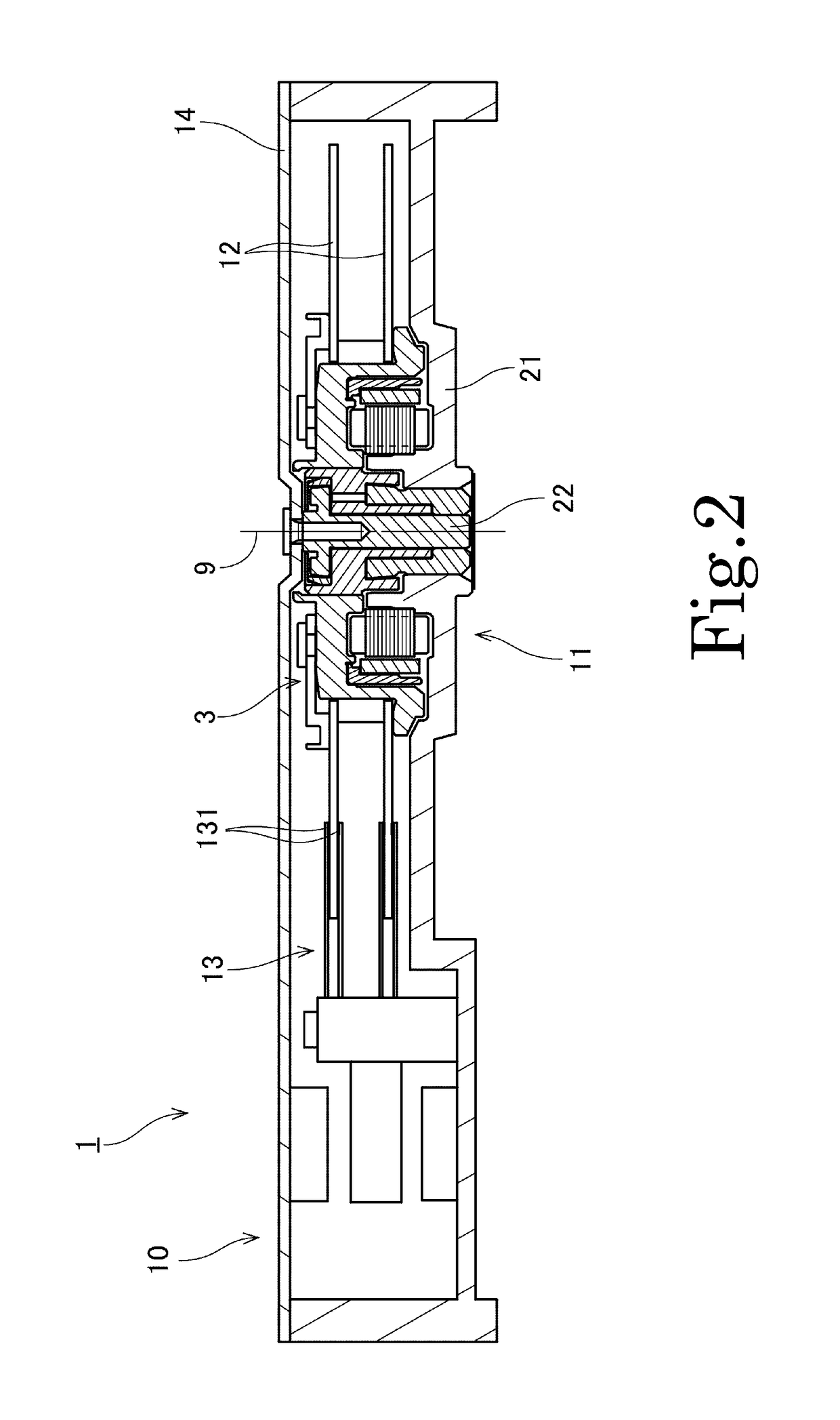
[0017]Hereinafter, motors and disk drive apparatuses according to preferred embodiments of the present invention will be described. It is assumed herein that a direction parallel or substantially parallel to a central axis of a motor is referred to by the term “axial direction”, “axial”, or “axially”, that directions perpendicular or substantially perpendicular to the central axis of the motor are each referred to by the term “radial direction”, “radial”, or “radially”, and that a direction along a circle centered on the central axis of the motor is referred to by the term “circumferential direction”, “circumferential”, or “circumferentially”. It is also assumed herein that an axial direction is a vertical direction, and that a side on which a top cover is arranged with respect to a base plate is an upper side, and the shape of each member or portion and relative positions of different members or portions will be described based on the above assumptions. It should be noted, however,...


PUM

PropertyMeasurementUnit
radial widthaaaaaaaaaa
areaaaaaaaaaaa
axial dimensionaaaaaaaaaa

Abstract

A rotating portion of a motor includes a magnet, a yoke, and a hub. An upper portion of the yoke is fixed to the hub. The yoke includes a first inner circumferential surface radially opposite to an outer circumferential surface of the magnet with a first gap intervening therebetween, and a second inner circumferential surface radially opposite to the outer circumferential surface of the magnet with a second gap intervening therebetween below the first inner circumferential surface. The second inner circumferential surface is parallel or substantially parallel to the outer circumferential surface of the magnet, and is located radially outward of the first inner circumferential surface. An adhesive is provided in at least a portion of the first gap. No adhesive is provided in at least a lower axial end portion of the second gap.

Description

BACKGROUND OF THE INVENTION[0001]1. Field of the Invention[0002]The present invention relates to a motor and a disk drive apparatus.[0003]2. Description of the Related Art[0004]Spindle motors arranged to rotate disks are typically installed in hard disk apparatuses and optical disk apparatuses. Such a spindle motor includes a stationary portion fixed to a housing of the apparatus, and a rotating portion arranged to rotate while supporting the disk(s). The spindle motor is arranged to produce a torque by magnetic flux generated between a stator and a magnet, whereby the rotating portion is caused to rotate with respect to the stationary portion. A known spindle motor is described, for example, in JP-A 2006-331558.[0005]A rotating portion of the spindle motor described in JP-A 2006-331558 includes a rotor hub on which a disk is mounted, a rotor yoke, and a magnet. The rotor yoke is fixed to an inner circumferential surface of the rotor hub. In addition, an inner circumferential surfac...

Claims


Application Information

Patent Timeline
Patent Type & Authority Patents(United States)
IPC IPC(8): H02K1/30G11B25/04H02K1/27G11B19/20H02K15/03
CPCH02K1/30G11B19/20G11B19/2045G11B25/043H02K1/2786G11B19/2009G11B19/2018H02K15/03H02K2201/03H02K1/2788
Inventor OCHITANI, SHUNICHIYAMAUCHI, WATARUMAEDA, MASAYUKI
Owner NIDEC CORP
Why Eureka
Try Eureka