Processing method of pipe clamp parts

A processing method and parts technology, which is applied in the processing field of catheter clamp parts, can solve the problems of unguaranteed product quality, difficult to meet the opening size, and large springback of parts, so as to achieve good product roundness and ensure the outer circle size and high appearance quality and shape precision

Active Publication Date: 2015-10-28
GUIZHOU AEROSPACE PRECISION PRODS
View PDF3 Cites 0 Cited by
  • Summary
  • Abstract
  • Description
  • Claims
  • Application Information

AI Technical Summary

Problems solved by technology

Due to the special structure and shape of the pipe clamp parts and high quality requirements, the following problems exist in the actual processing of the clamp parts using the original process and mandrel forming: after wire cutting processing, there are wire holes on the tongue, making the shape of the tongue Affected, the cutting time is long; when both ends press the small ears at the same time, the product specifications are more, which increases the number of molds. At the same time, the mold structure is more complicated, the forming shape is not good, and there is a tongue in the center of the product. Wounded tongue piece; when rolling and forming, it is manually shaped after rolling on the mandrel, which often causes the parts to have large springback after bending, the opening size is difficult to meet, the roundness error is large, the two waist-shaped holes are dislocated after bending, and the shape The precision is low, so that the product cannot meet the requirements and is scrapped, resulting in a large loss
Therefore, using the original process and tooling processing, not only the production efficiency is low, the production cost is high, the processing cycle is long, and the quality of the product cannot be guaranteed.

Method used


Image

  • Processing method of pipe clamp parts
  • Processing method of pipe clamp parts
  • Processing method of pipe clamp parts

Examples


Embodiment Construction

[0027] The present invention will be further described in detail below in conjunction with the accompanying drawings and embodiments.

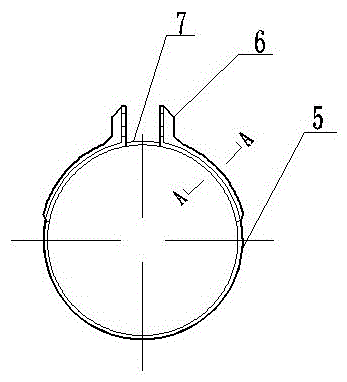
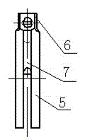
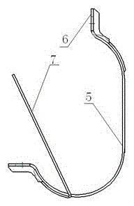
[0028] First introduce the product of the present invention, that is, the structure of the catheter clamp parts, first look at figure 1 , figure 1 It is the structural representation of the product of the present invention, that is, the catheter clamp part. We can see from the figure that the main part of the catheter clamp part of the present invention is an annular hoop 5, and the closed ends of the hoop ring 5 are respectively provided with There are two small ears 6, and a tongue 7 is embedded inside the hoop 5. When the hoop 5 is rolled and closed, the tongue 7 closes the opening between the small ears 6 of the hoop 5. Look figure 2 , Figure 4 , from the side and cross-section, there is a groove in the center of the hoop 5, and the tongue 7 is embedded in the groove. In addition, two small ears 6 are respectively provided with a wais...


PUM


Abstract

The invention discloses a processing method and tooling for a tube clamp part. The processing method and the tooling are used for processing a circular tube clamp part of which both ends are provided with small lugs. The circular tube clamp part also comprises a clamp ring and a tongue sheet. When the circular tube clamp part is formed by the processing method and the tooling, a closed die processing method is adopted. When the circular tube clamp part is bent, the die converges to the middle, and the circular tube clamp part is formed in a die cavity, so the outer circular size and the appearance quality of the circular tube clamp part are ensured, and the rebound is reduced. The tooling has the advantages that a half type upper and lower symmetrical structure is adopted, the structure is simple, the manufacture is easy, the shape is small, the manufacture cost is low, the shape of the die cavity of the tooling is the same as the shape of the circular tube clamp part, the circularity of the bent circular tube clamp part is good, the shape precision is high, and the production efficiency is high. The requirements on operation skills of operators are low, the assembly and disassembly are convenient, the production cost is low, and the circular tube clamp part has good size uniformity and stable quality.

Description

technical field [0001] The invention relates to a processing method and a tooling for a catheter clamp part, belonging to the technical field of clamps. Background technique [0002] Clamp products are mainly used for fastening oil pipes and lines on aviation, aerospace, and ships. Because they are exterior decorations, they have high requirements for performance and appearance quality, high product added value, and wide application. However, due to many models and specifications , The batch size is not large, and the production cycle is short, which brings great difficulties to the processing method and production organization. attached figure 1 The catheter clamp part shown is one of the common clamp parts. This part is a ring-shaped catheter clamp part with small ears at both ends. The part also includes a hoop ring and a tongue. The traditional processing of this The processing technology of this catheter clamp part is: blanking → fitter punches the thread hole of the ...

Claims


Application Information

Patent Timeline
Patent Type & Authority Patents(China)
IPC IPC(8): B21D53/18
Inventor 彭南宁范旭周绚谭任帮
Owner GUIZHOU AEROSPACE PRECISION PRODS
Why Eureka
Try Eureka