Intravascular catheter assembly

a technology of intravascular catheter and assembly, which is applied in the field of intravascular catheter systems, can solve the problems of inability to ensure whether the puncture is correct, inability to detect the moment of venipuncture, and inability to allow however some amount of blood to flow into the flashback chamber, so as to achieve the effect of fast and accurate method

Active Publication Date: 2017-07-11
OPTOMEDITECH
View PDF43 Cites 3 Cited by
  • Summary
  • Abstract
  • Description
  • Claims
  • Application Information

AI Technical Summary

Benefits of technology

[0019]The provision of the adapter makes it possible to isolate the light source and the electronic module from the remaining components of the assembly. Unlike the prior art solutions, in which the light source is arranged in a flashback chamber and thus gets into contact with blood during use, the light source and the electronic module of the present invention, which are usually the more expensive components of the entire assembly, can be reused without a need for sterilization. This significantly reduces the costs associated with usage of the assembly, because the relatively cheap components, i.e. the tubular introducer needle, the cannula tubing and the adapter, to which the light guide is fixed, can be disposed of after use, while the more expensive components are reusable.
[0050]In still another aspect of the invention, a fast and accurate method for placing a peripheral intravascular catheter and for performing at least initial stages of placement of central venous catheter into a blood vessel is provided.

Problems solved by technology

The major disadvantage of the known method is that, the moment of venipuncture may be detected only by visual monitoring of blood appearance in a flashback chamber.
By means of a conventional system, disclosed above, it is impossible to assure whether blood vessel is punctured correct, i.e. whether the needle tip entered the lumen of the blood vessel and is positioned correctly therein.
Situations, when the needle punctures blood vessel throughout and hits surrounding soft tissue afterwards, allowing however some amount of blood to flow into a flashback chamber, are thus undetectable.
Improperly placed catheter may further cause damages to blood vessel walls and make a patient to suffer unnecessary stress and complications.
However, some groups of patients may have small and thin blood vessels so that even upon successful entry of the needle tip inside the lumen of the vein, some light may still be visible on skin from the outside, thus causing confusion.
However, when a blood vessel to be punctured has a relatively small diameter (cf. FIG. 10A: small vein, light guide is in close proximity to the needle tip), even in case of a successful penetration of the blood vessel some light 501 may possibly still ‘leak’, creating an illuminated spot to be observed on the skin and thus causing confusion.
Therefore complete absorption of light cannot physically be accomplished for the reason that the vein may be too thin and small to accommodate the needle tip over its whole diameter.
This may lead to blood vessel damage during advancement of cannula tubing.

Method used


Image

  • Intravascular catheter assembly
  • Intravascular catheter assembly
  • Intravascular catheter assembly

Examples


Embodiment Construction

[0087]Detailed embodiments of the present invention are disclosed herein with the reference to accompanying drawings. The same reference characters are used throughout the drawings to refer the same members. Following citations are used for the members:

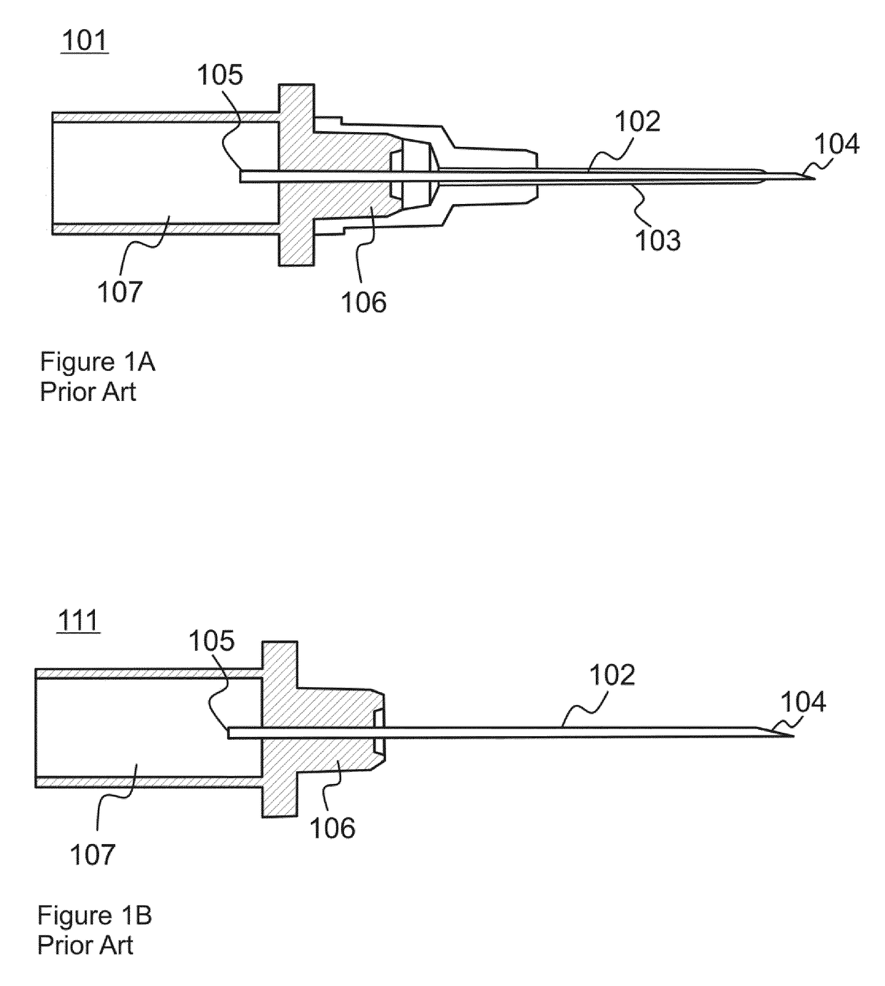
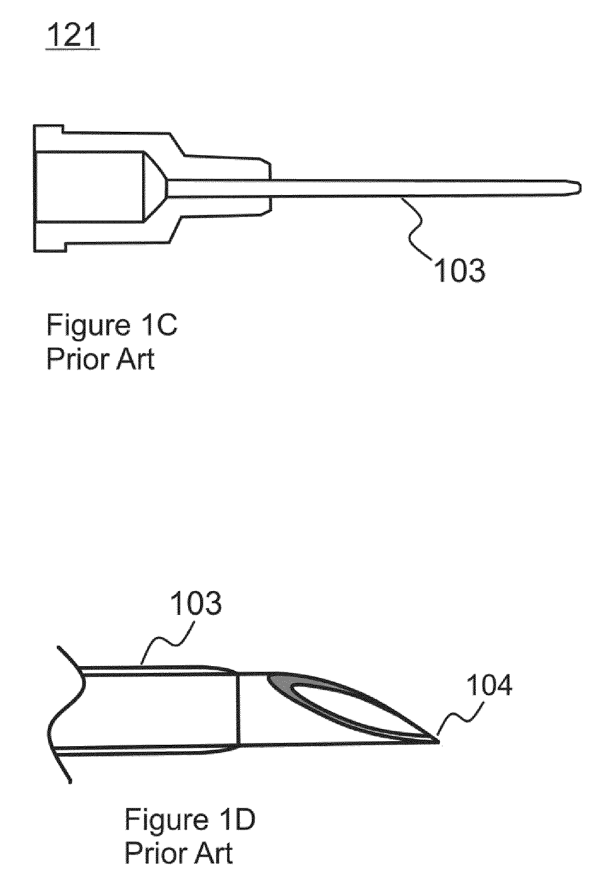
[0088]Prior Art:[0089]101—intravascular catheter assembly;[0090]111—introducer needle provided with a connection hub;[0091]102—metallic needle member;[0092]121—cannula;[0093]103—cannula tubing;[0094]104—insertion (distal) end of the needle member of the introducer needle;[0095]105—chamber (proximal) end of the needle member of the introducer needle;[0096]106—connection hub of the introducer needle;[0097]107—flashback chamber formed by an inner space of the connection hub (106);[0098]108—blood.

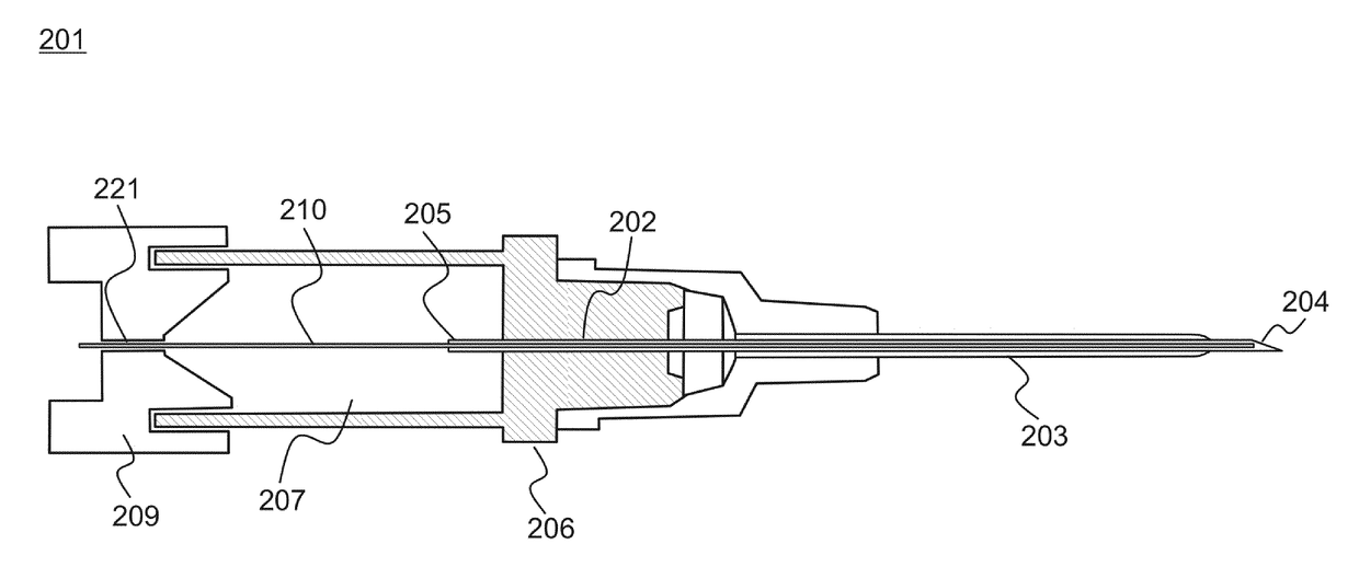
[0099]Present Disclosure:[0100]201—intravascular catheter assembly in accordance with some embodiment of the invention;[0101]211—introducer needle provided with a connection hub;[0102]202—metallic needle member;[0103]203—cannula tubing;[0104]204—...


PUM


Abstract

A peripheral intravascular catheter assembly comprising a tubular introducer needle and an adapter connected to the proximal end of the light guide. An introducer needle comprises a connection hub and a needle member. The needle member has a lumen, a distal end and a proximal end. The assembly can include a cannula tubing surrounding at least a portion of the needle member, with at least one light source and with an electronic module, configured to power the light source. The light guide has a distal end and a proximal end and extends along the lumen of the needle member. The adapter may be connected to the electronic module to the connection hub of the introducer needle so that light emitted by the light source is capable of entering the light guide, but blood flowing through the lumen of the needle member is prevented from contacting the light source.

Description

CROSS-REFERENCE TO RELATED APPLICATIONS[0001]The present application is a U.S. National Phase Application of International Application No. PCT / EP2012 / 066246, filed Aug. 21, 2012.FIELD OF THE INVENTION[0002]The present invention relates to medical intravascular catheter systems and in particular to intravascular catheter assemblies.BACKGROUND[0003]Intravascular catheter systems, such as peripheral intravenous catheters or central venous catheters, for example, are essential in modern medical practice. Catheter systems are commonly used for fluid infusion or withdrawal, or for monitoring various physiological parameters, such as blood pressure, pH and blood gas tensions. Catheter systems may be also used for introducing and locating probes, such as blood gas- or blood pressure probes.[0004]Conventional method of placing the catheter into a blood vessel using over-the-needle technique comprises skin puncture with an introducer needle, moving the needle in surrounding tissues forward to...

Claims


Application Information

Patent Timeline
Patent Type & Authority Patents(United States)
IPC IPC(8): A61M25/01A61M5/42A61M25/06A61B5/153A61M5/46A61B5/155A61B5/15
CPCA61M25/0105A61B5/1535A61B5/150748A61M5/427A61M5/46A61M25/0606A61M25/0693A61B5/1422A61B5/15003A61B5/155A61B5/15016A61B5/150389A61B5/150503A61B5/150992A61M25/0618A61M2025/0166
Inventor GASPARYAN, LEVONROMBERG, HANS
Owner OPTOMEDITECH
Why Eureka
Try Eureka