
Pneumatic tire

a technology of pneumatic tires and pneumatic cylinders, which is applied in the direction of non-skid devices, vehicle components, transportation and packaging, etc., can solve the problems of reduced steering stability on wet road surfaces, increased risk of water discharge, and reduced steering stability on dry road surfaces, so as to improve steering stability on snow-covered road surfaces, maintain the stiffness of the shoulder ribs, and improve the effect of steering stability

Active Publication Date: 2017-08-01
THE YOKOHAMA RUBBER CO LTD
View PDF22 Cites 2 Cited by
  • Summary
  • Abstract
  • Description
  • Claims
  • Application Information

AI Technical Summary

Benefits of technology

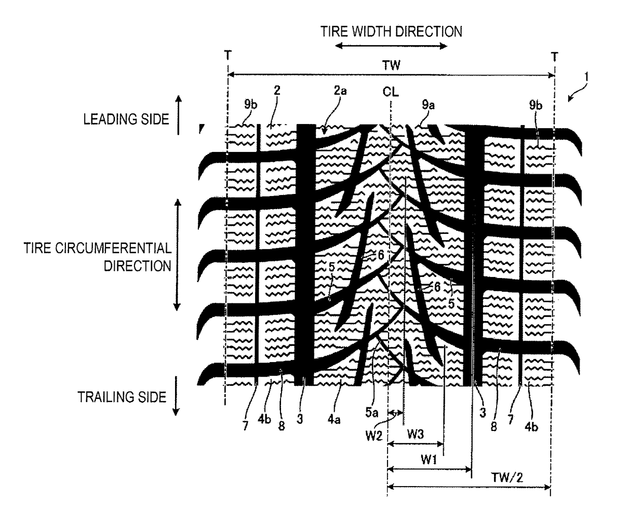
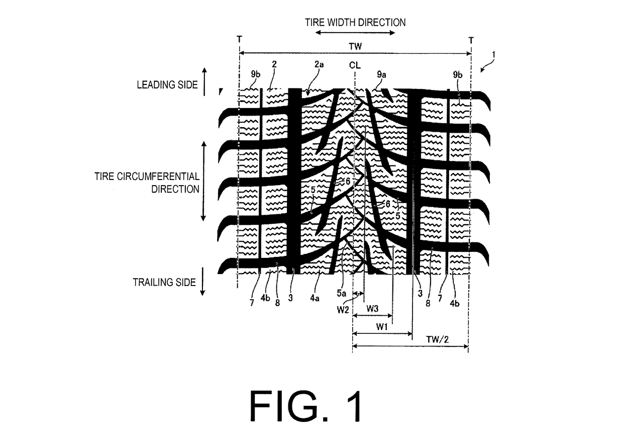
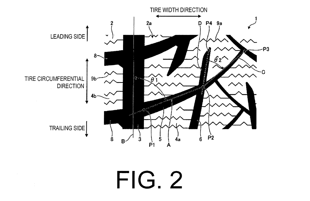
[0007]The present technology provides a pneumatic tire that can improve steering stability on snow-covered road surfaces without causing a deterioration in steering stability on dry and wet road surfaces. A pneumatic tire of the present technology includes, in a tread portion, a center rib formed by two circumferential main grooves extending along a tire circumferential direction in a center of a tire width direction including a tire equatorial plane. A main inclined groove and an auxiliary inclined groove are formed in the center rib. The main inclined groove is provided so as to incline with respect to the tire circumferential direction in a manner so as to become distanced from the tire equatorial plane from a leading side toward a trailing side in a tire rotational direction, a trailing end communicating with the circumferential main groove, a plurality of the main inclined grooves being juxtaposed in the tire circumferential direction and disposed alternately in the tire circumferential direction on both sides of the tire equatorial plane. The auxiliary inclined groove is provided so as to incline with respect to the tire circumferential direction in a manner so as to become distanced from the tire equatorial plane from the leading side toward the trailing side in the tire rotational direction, a leading end and a trailing end terminating within the center rib while intersecting at least two of the main inclined grooves, a plurality of the auxiliary inclined grooves being juxtaposed in the tire circumferential direction and disposed alternately in the tire circumferential direction on both sides of the tire equatorial plane.
[0008]According to this pneumatic tire, water discharge performance and snow discharge performance are improved so that steering stability on wet road surfaces is maintained and steering stability on snow-covered road surfaces can be effectively improved by providing, in the center ribs in the center of the tire width direction of the tread portion, inclined grooves that extend from the center of the tire width direction (near the tire equatorial plane) toward the outer side of the tire width direction. Moreover, since an auxiliary inclined groove is provided that intersects at least two main inclined grooves while a leading end and a trailing end terminate within a center rib, and since the both inclined grooves are disposed alternately in the tire circumferential direction, stiffness of the tread portion is maintained such that steering stability on dry road surfaces can be ensured. As a result, steering stability on snow-covered road surfaces can be improved without causing a deterioration in the steering stability on dry and wet road surfaces.

Problems solved by technology

Although making the blocks narrower may be effective with respect to snow-covered road surfaces, there is a risk that steering stability on dry road surfaces may be reduced since the stiffness of the blocks is reduced.
Additionally, there is a risk that water discharge performance is made worse and steering stability on wet road surfaces may be reduced since the grooves that connect with the inclined grooves are inclined in the direction opposite the inclined grooves and thus work against the action of the inclined grooves to guide water from the center circumferential flat plane to both sides and thus return the water to the center circumferential flat plane side.

Method used


Image

  • Pneumatic tire
  • Pneumatic tire
  • Pneumatic tire

Examples


working examples

[0065]In the working examples, performance testings for steering stability on dry, wet and snow-covered road surfaces were performed on a plurality of types of pneumatic tires under different conditions (see FIG. 3).

[0066]The performance testing for steering stability included assembling pneumatic tires having a tire size of 255 / 40 R19 on regular rims (a “standard rim” defined by the Japan Automobile Tyre Manufacturers Association Inc. (JATMA), a “Design Rim” defined by the Tire and Rim Association, Inc. (TRA), or a “Measuring Rim” defined by the European Tyre and Rim Technical Organisation (ETRTO)). The pneumatic tires were inflated to an air pressure of 250 [kPa] and mounted on a test vehicle (3.0 liter class four-wheel drive sedan).

[0067]In the evaluation method of steering stability on a dry road surface, a sensory evaluation of initial response by a driver when the test vehicle changed traveling lanes while traveling on a straight test course on a dry road surface at 200 [km / h]...


PUM


Abstract

A center rib is formed by two circumferential main grooves. A main inclined groove and an auxiliary inclined groove are formed in the center rib. The main inclined groove is inclined with respect to the tire circumferential direction to become distanced from the tire equatorial plane from a leading side toward a trailing side in a tire rotational direction, a plurality of the main inclined grooves being juxtaposed in the tire circumferential direction and disposed alternately in the tire circumferential direction on both sides of the tire equatorial plane. The auxiliary inclined groove inclines with respect to the tire circumferential direction to become distanced from the tire equatorial plane from the leading side toward the trailing side in the tire rotational direction, a leading end and a trailing end terminating within the center rib while intersecting at least two of the main inclined grooves.

Description

PRIORITY CLAIM[0001]Priority is claimed to Japan Patent Application Serial No. 2011-128493 filed on Jun. 8, 2011.BACKGROUND[0002]Technical Field[0003]The present technology relates to a pneumatic tire that improves steering stability on snow-covered road surfaces without causing a deterioration in steering stability on dry and wet road surfaces.[0004]Related Art[0005]Conventionally, the object of a pneumatic tire (a tread of an automobile pneumatic tire) described in, for example, Japanese Unexamined Patent Application Publication No. H06-278412A is to reduce hydroplaning and improve winter performance. The pneumatic tire is equipped with a center block column extending in the tire circumferential direction and block columns arranged in a shoulder portion and separated from the center block column by two circumferential grooves. The pneumatic tire is devised to guide water from a center circumferential flat plane to both sides by providing grooved blocks of the center block column, ...

Claims


Application Information

Patent Timeline
Patent Type & Authority Patents(United States)
IPC IPC(8): B60C11/11B60C11/03B60C11/12
CPCB60C11/0302B60C11/1218B60C2011/0341B60C2011/0348B60C2011/0365B60C2011/0372B60C2011/0374
Inventor SHINZAWA, TATSURO
Owner THE YOKOHAMA RUBBER CO LTD
Learn More