
Melting device for consolidating contaminated scrap

a technology of contaminated scrap and melting device, which is applied in the field of contaminated scrap melting device, can solve the problems of reducing the volume of the repository and thus the cost, accumulating high-level radioactive scraps, and unable to return to the normal material cycle, so as to reduce the volume of radioactively contaminated materials, and reduce the volume of radioactive contaminated materials.

Active Publication Date: 2017-08-01
ALD VACUUM TECH GMBH
View PDF15 Cites 0 Cited by
  • Summary
  • Abstract
  • Description
  • Claims
  • Application Information

AI Technical Summary

Benefits of technology

[0017]It is the object of this invention to provide a melting device for reducing the volume of radioactively contaminated material, which makes it possible to significantly reduce the transport of radioactive material.
[0018]The object is achieved by the subject matter of the claims. The present invention provides an improved method by providing a novel mobile melting device and a method as defined in the claims. The invention provides a facility and a method capable of achieving a reduction in volume of such radioactively contaminated material as is obtained from the dismantling of nuclear facilities (hereinafter: “material to be to melted”). The facility can be operated economically and causes no risks to human health and the environment in operation.

Problems solved by technology

Medium level contaminated scraps and high level radioactive scraps may also be accumulated.
These scraps can no longer be returned into the normal material cycle and have to be disposed of in a repository.
When storing unconsolidated material many cavities would remain, which would considerably increase the repository volume and thus the costs.
Furthermore, such scrap heaps provide a very large surface area, from which radionuclides could be carried off or released.
Thus, additionally large amounts of contaminated waste and dust are obtained as secondary waste.The nuclear controlled area of these plants is relatively large.Known plants are stationary plants to which the radioactively contaminated scrap has to be transported.Scraps containing reactive metals, such as magnesium, cannot be melted.Scrap components which develop harmful vapors, such as cadmium, can only be melted in a restrictive way.Volatile radioactive isotopes cannot be retained.The dismantling of such plants is very complex.
This means that contaminated material has to be transported from the demolition site to the waste disposal centers, which increases the costs for a large transport volume of nuclear material.
However, the furnace is not hermetically sealed.
Thus, the facility described therein cannot be used as a mobile unit.
Thus, the facility is neither sealed hermetically nor transportable.
Common to all is that the melting devices are not transportable or are transportable only with a very large expense.
However, transports of radioactive materials are risky and regularly meet with resistance from the population.

Method used


Image

  • Melting device for consolidating contaminated scrap
  • Melting device for consolidating contaminated scrap
  • Melting device for consolidating contaminated scrap

Examples


Embodiment Construction

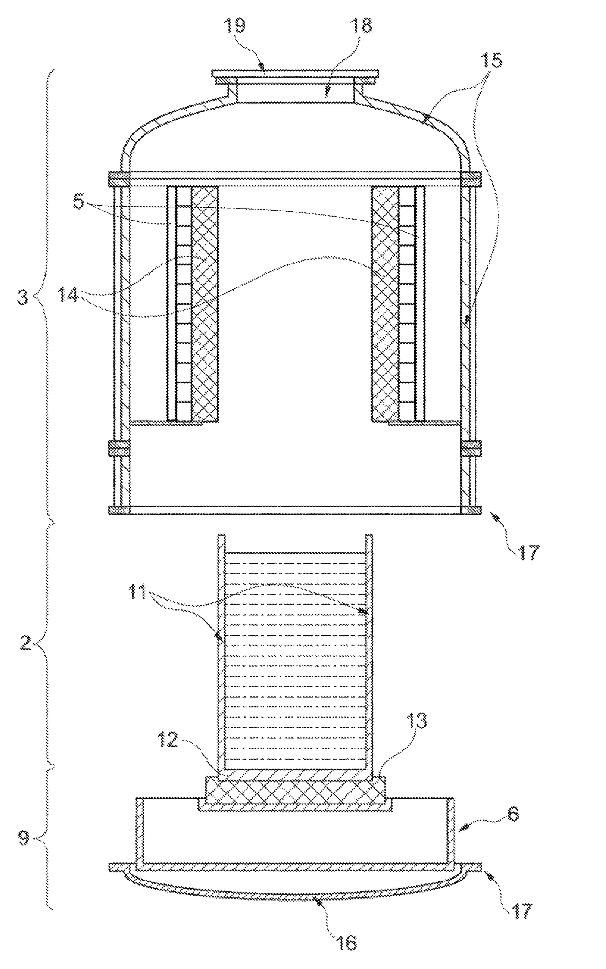
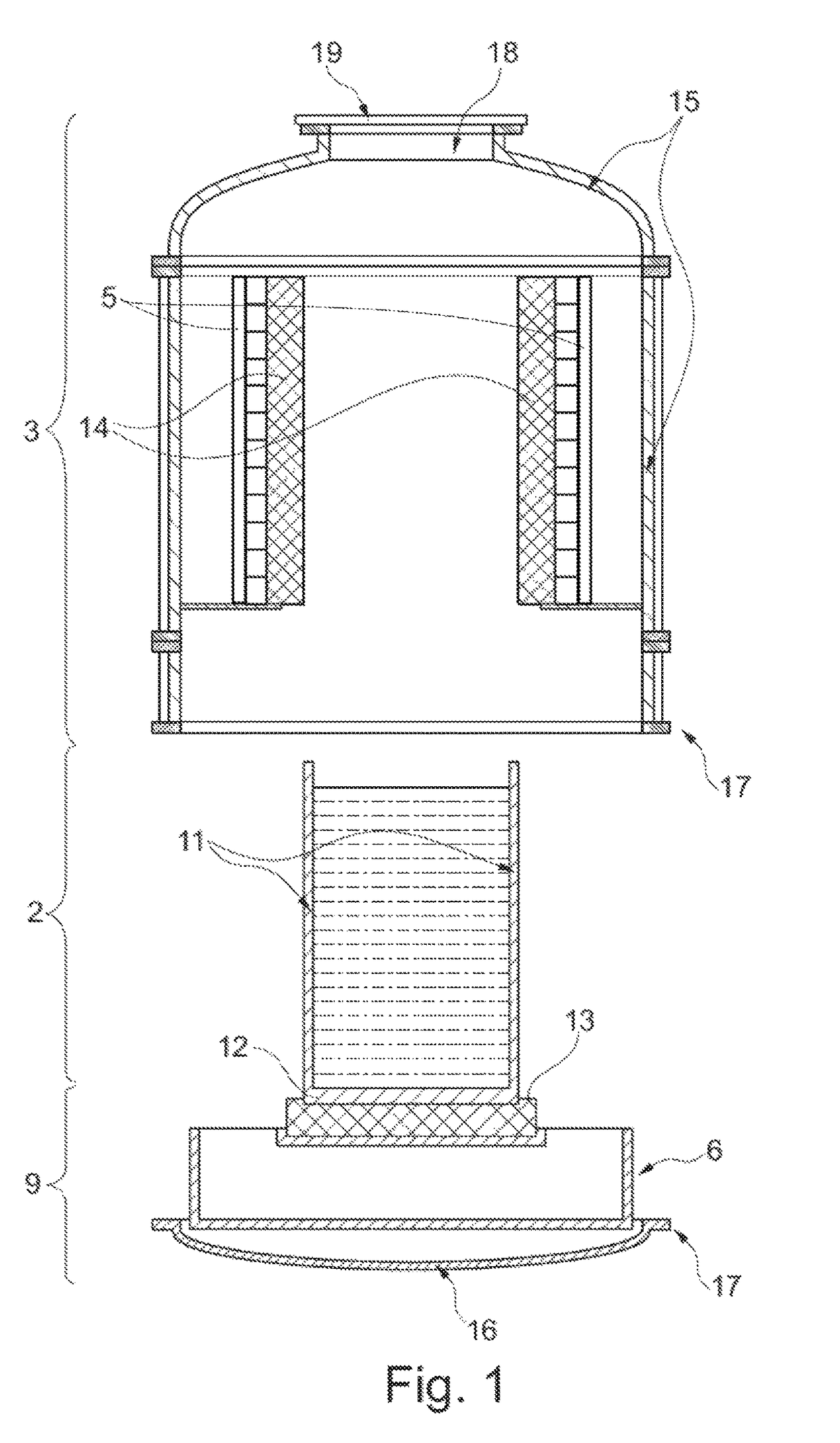
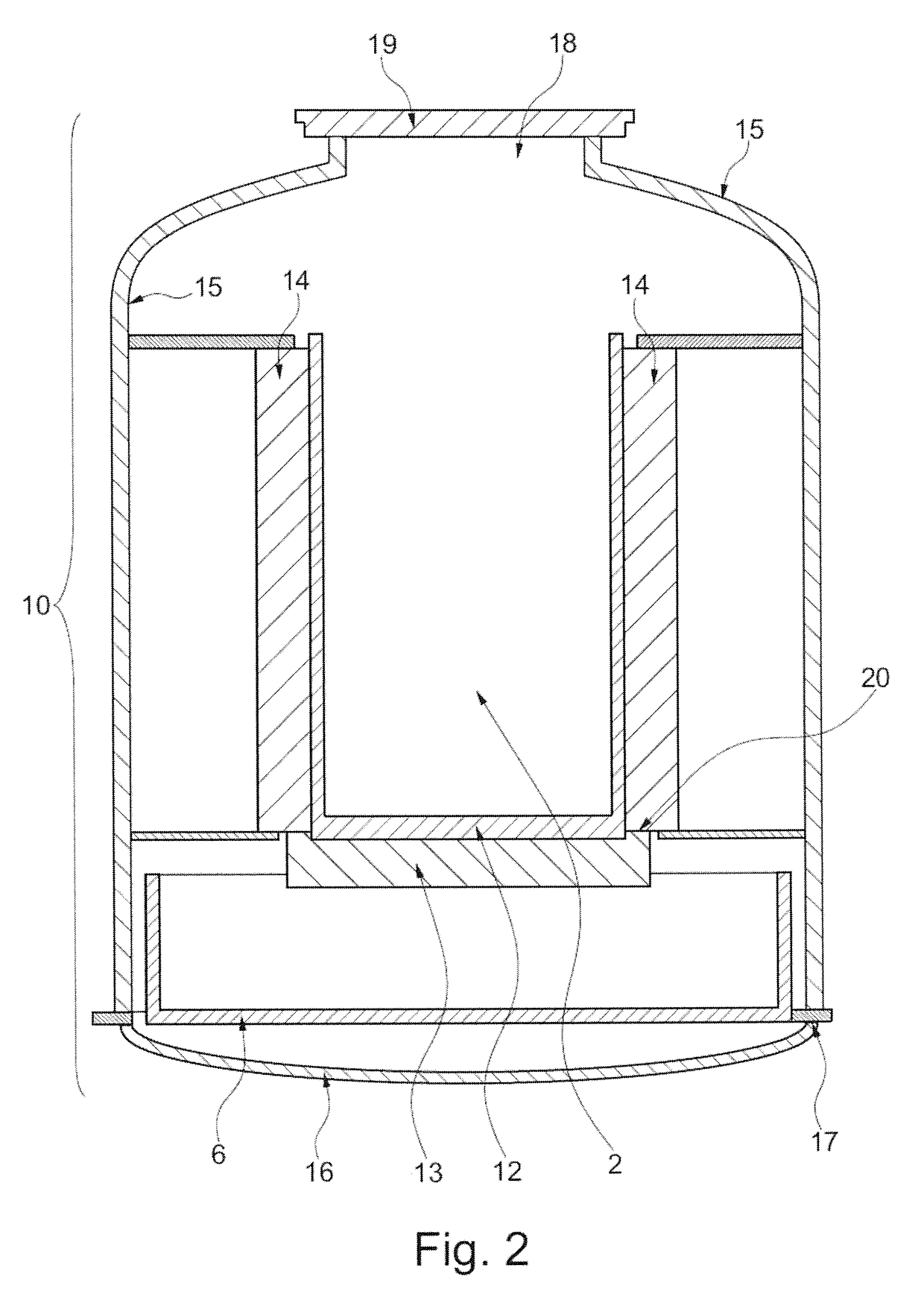
[0019]The melting device according to the invention is a mobile melting device comprising a crucible base and a crucible chamber which is suitable for receiving the crucible. The crucible base includes a chamber bottom and the crucible chamber comprises a shell. The melting device comprises a transport means which is capable to move the crucible base together with the crucible from a first position outside the crucible chamber to a second position within the crucible chamber (also: melting position). The chamber bottom and the shell are configured so that they together form a gas-tight furnace enclosure in the second position.

[0020]The crucible can thus be moved from a place outside the crucible chamber to a place within the crucible chamber and vice versa. In operation the transport means is preferably arranged below the crucible chamber so that the crucible can be lifted upwardly into the crucible chamber by means of the transport means. The transport means can be a scissor lift t...


PUM

PropertyMeasurementUnit
oxygen partial pressureaaaaaaaaaa
massaaaaaaaaaa
massaaaaaaaaaa

Abstract

A mobile melting device for consolidating contaminated scrap and to a corresponding method. The melting device has a crucible chamber and a crucible base. The crucible is arranged on the crucible base during operation, and the crucible base and the crucible chamber together form a gas-tight furnace housing. It is thus possible to carry out the method in a vacuum or under protective gas such that even a reactive material can be consolidated. The melting device can be assembled and disassembled with little effort.

Description

FIELD OF THE INVENTION[0001]The present invention relates to a melting device for consolidating contaminated scrap and a consolidation method that can be performed by use of the melting device.BACKGROUND OF THE INVENTION[0002]During the dismantling of nuclear plants, such as nuclear power plants, research centers, uranium enrichment plants and reprocessing plants contaminated scraps are accumulated which, for example, fall into the category “low level radioactive waste”. These scraps may possibly be decontaminated by the remelting process and returned into the normal material cycle. Medium level contaminated scraps and high level radioactive scraps may also be accumulated. These scraps can no longer be returned into the normal material cycle and have to be disposed of in a repository. To keep costs of the repository as low as possible it is necessary to consolidate the volume of the accumulated scrap into a massive block by melting. The present invention describes a melting device a...

Claims


Application Information

Patent Timeline
Patent Type & Authority Patents(United States)
IPC IPC(8): F27B14/00G21F9/00F27B14/04F27B14/08G21F9/30G21D1/00
CPCG21F9/308F27B14/04F27B14/08G21F9/008F27B2014/0831G21D1/003
Inventor FRANZ, HENRIKGROSSE, KARL-HEINZHOLZ, MARKUSPROTZMANN, MICHAEL
Owner ALD VACUUM TECH GMBH
Learn More