Method and apparatus for efficient generation of compact waveform-based timing models

a waveform-based timing model and efficient technology, applied in the direction of instruments, computing, electric digital data processing, etc., can solve the problems of non-ideal transition and runtime intensive, and achieve the effect of reducing runtime and memory

Active Publication Date: 2017-08-08
CADENCE DESIGN SYST INC
View PDF4 Cites 4 Cited by
  • Summary
  • Abstract
  • Description
  • Claims
  • Application Information

AI Technical Summary

Benefits of technology

[0006]It is an object of the disclosed system and method to reduce runtime and memory required to compute waveforms in the generation of a timing model.
[0007]It is another object of the disclosed system and method to reduce a size of a timing model, without reducing accuracy of the model.
[0008]It is yet another object of the disclosed system and method to reduce a required number of waveforms and other data values in a representation of a circuit path, without reducing accuracy of the representation.
[0009]It is still another object of the disclosed system and method to remove redundancy in representations of pluralities of circuit paths.

Problems solved by technology

One quality of a circuit modeled in an ETM is the non-ideal transition (such as ramp-up or ramp-down of voltage) of signals as they traverse various components.
However, when modeling advanced technology nodes, this assumption has proven too inexact, and therefore actual sample points which more closely characterize input and output waveforms are computed to replace these parameters.
Additionally, determining each output slew involves simulating propagation of the corresponding input slew step-by-step through the circuit path, which is particularly runtime intensive when the slews are replaced with waveforms.

Method used

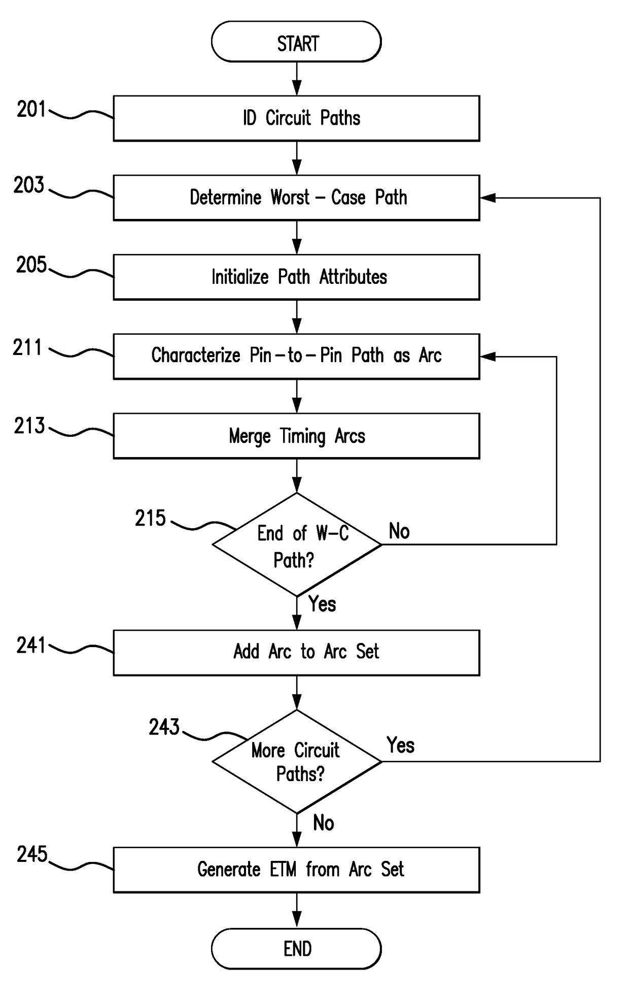
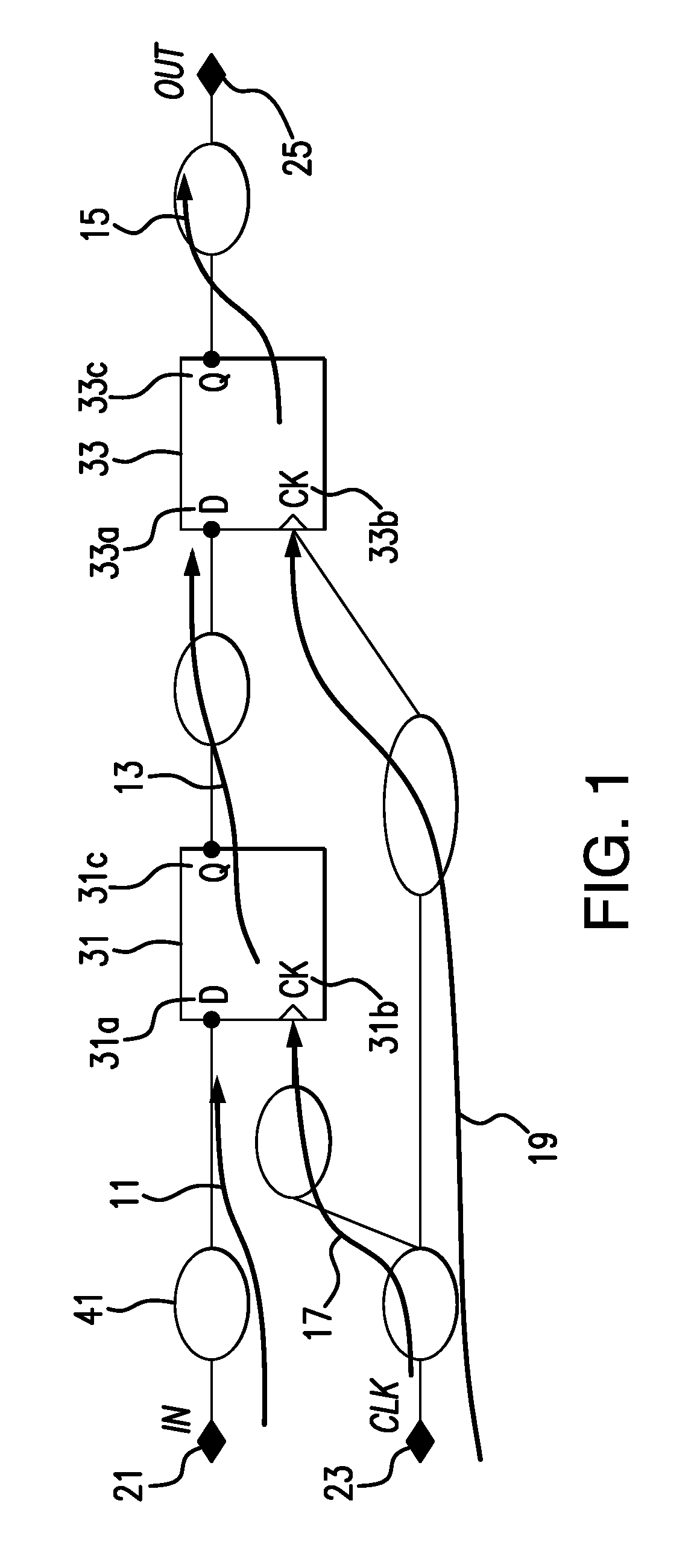
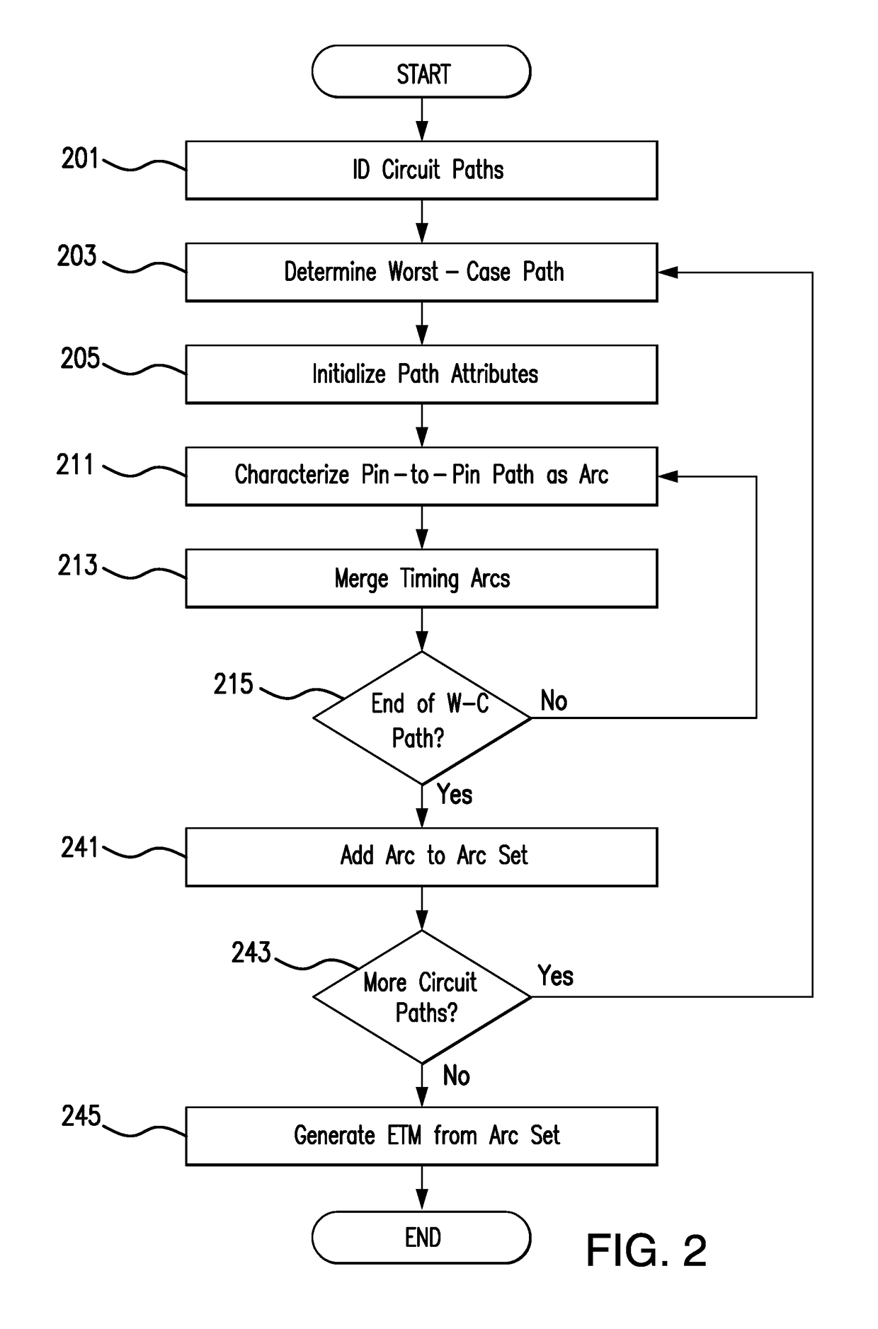

Image

  • Method and apparatus for efficient generation of compact waveform-based timing models
  • Method and apparatus for efficient generation of compact waveform-based timing models
  • Method and apparatus for efficient generation of compact waveform-based timing models

Examples


Embodiment Construction

[0044]Reference will now be made in detail to exemplary embodiments, which are illustrated in the accompanying drawings, wherein like reference numerals refer to the like elements throughout. The embodiments are described below in order to explain the disclosed system and method by referring to the figures.

[0045]Section headings are included in this Detailed Description. It is noted that these section headings are for convenience only and should not be interpreted as limiting the scope of the claimed invention in any way.

1. Extracted Timing Models Generally

[0046]Static timing analysis (STA) is a methodology, well-known in the art, to assess the timing of any given digital circuit using software techniques and certain models that provide relevant characteristics of the digital circuit. At the highest level of analysis, STA considers the timing of a signal over all possible paths through the circuit to confirm that said timing meets the requirements of the design, and in some cases de...


PUM


Abstract

For a circuit path to be represented in a timing model, a set of propagating waveforms substantially converges through waveform stabilization to a uniform waveform at a waveform invariant node and all pins following. The circuit path is decomposed at the waveform invariant node into first and second portions, which are characterized as first and second timing arcs. In computing output slew and delay values, the first timing arc generation factors only a single output load of the waveform invariant node, and the second timing arc generation factors only the uniform waveform. Similarly, a setup arc employs the uniform waveform rather than multiple clock input waveforms in computing setup / hold values. Simulation of waveform propagation is also simplified by simulating only the uniform waveform for the second portion. Additionally, the first arc may be shared between a plurality of circuit paths which share an input pin and the waveform invariant node.

Description

BACKGROUND OF THE INVENTION[0001]The subject system and method are generally directed to the efficient generation of highly compact timing models for use in timing analysis of circuit designs. More specifically, the system and method include identification of a waveform invariant node for a given circuit path and optimized generation and configuration of a timing model based thereon.[0002]With the increase in the size and complexity of circuit designs, divide-and-conquer methodologies executed using hierarchical design implementation and sign-off have become the preferred design approach. One of the extensively employed methodologies for hierarchical design implementation is based on the Extracted Timing Model (ETM). An ETM encapsulates the timing information of circuit paths of a given block, often although not necessarily in Synopsys Liberty Format (.lib format). The ETMs of different blocks of a design are extracted and plugged-in at the top-level for performing top-level timing ...

Claims


Application Information

Patent Timeline
Patent Type & Authority Patents(United States)
IPC IPC(8): G06F9/455G06F17/50
CPCG06F17/5031G06F30/3312
Inventor SAURABH, SNEHKUMAR
Owner CADENCE DESIGN SYST INC
Why Eureka
Try Eureka