Self-propelled harvesting machine

a harvesting machine and self-propelled technology, applied in the direction of steering parts, agricultural machines, guiding agricultural machines, etc., can solve the problems of extreme shear force between the external profiling of the traction means and the ground, and the inability to drive the field to be harvested, so as to improve the straight-ahead running of the tracked vehicle and improve the steerability of the self-propelled combine harvester

Active Publication Date: 2017-08-15
CLAAS SELBSTFAHRENDE ERNTEMASCHINEN GMBH
View PDF13 Cites 3 Cited by
  • Summary
  • Abstract
  • Description
  • Claims
  • Application Information

AI Technical Summary

Benefits of technology

[0013]The invention improves the steerability of a harvesting machine operated with a front harvesting attachment, without the ground contact areas of the two belt bands assigned to the ground drive being changed during travel around a curve or when the harvesting machine is turned.
[0017]According to the invention, the transmission of the harvesting machine transfers different drive torques to the two track roller units, which are disposed on the right and the left of the harvesting machine. Such arrangement results in generation of an additional moment about the vertical axis to support the travel around the curve. For this purpose, a hydraulic motor of a hydrostatic transmission is assigned to each of the drive shafts, the displacement volume of which is changed depending on the steering movement that is transferred from the steering mechanism to the steerable rear wheels. As a result, a substantial improvement of the turning properties of the harvesting machine is achieved such that the shear forces acting on the ground are markedly reduced. It also is advantageous that the ground contact areas of the track roller units remain unchanged during this turning procedure such that the favorable traction behavior and the low ground pressure is retained in the headland of the field to be harvested. Otherwise considerable ground damage would possibly occur in the region of the headland.
[0018]According to DE 41 93 720 T1, the steerability of a self-propelled combine harvester provided with a half-tracked drive also is improved, although, for this purpose, the combine harvester is raised in the rear region thereof in that the steerable wheels assume a greater portion of the load during a steering procedure and, to this end, the track roller unit is raised off the ground in the region of the support rollers and the deflection wheel. As a result, however, the steerable rear wheels and the drive wheel sink into the ground to an extreme extent under the additional load.
[0019]The ground contact area of the crawler track belts also is reduced in the arrangement provided according to DE 10 2011 114 536 A1 for improving the steerability of the self-propelled combine harvester provided with the half-tracked drives such that the ground pressure increases on the rest of the ground contact area.
[0020]The drive system provided according to DE 40 16 496 A1 is provided for a tracked vehicle having a full-chain drive, i.e., the vehicle does not have any steerable wheels of a corresponding steering axle in addition to the endless track. A piston-displacement actuating device having an arrangement of valves assigned to the individual hydraulic motors is provided so that the two hydraulic motors can always be set on the same control characteristic curve, regardless of which of the chains has the greater tractive resistance. This is intended to improve the straight-ahead running of the tracked vehicle.
[0023]The aforementioned at least two shiftable transmission ratio steps of the mechanical transmission are required due to the requirement of a transmission ratio spread between a maximum tractive force and corresponding end speeds. Due to the use of these shift stages, the necessary hydraulic transmission ratio spread is reduced and, therefore, efficiency is improved due to a more efficient hydraulic ground drive. In regard to the high overall transmission ratios required during field operation, hydraulic units having smaller sizes can be used, thereby resulting in weight and cost advantages.

Problems solved by technology

Without appropriate crawler drives, fields to be harvested usually cannot be driven on after relatively long rainy periods and / or the harvesting machine sinks into the ground so far that the ground condition in the resultant tracks is markedly worsened.
An appropriate track roller unit, which is preferably provided with a belt band, has a substantial disadvantage in that, during maneuvering, extreme shear forces occur between the external profiling of the traction means and the ground.
When traveling on an asphalt-covered road, the belt band undergoes increased wear during cornering or turning.
On the field, the shear forces cause the ground to tear, which is also unwanted, since this alters and damages the ground structure.

Method used


Image

  • Self-propelled harvesting machine
  • Self-propelled harvesting machine
  • Self-propelled harvesting machine

Examples


Embodiment Construction

[0034]The following is a detailed description of example embodiments of the invention depicted in the accompanying drawings. The example embodiments are presented in such detail as to clearly communicate the invention and are designed to make such embodiments obvious to a person of ordinary skill in the art. However, the amount of detail offered is not intended to limit the anticipated variations of embodiments; on the contrary, the intention is to cover all modifications, equivalents, and alternatives falling within the spirit and scope of the present invention, as defined by the appended claims.

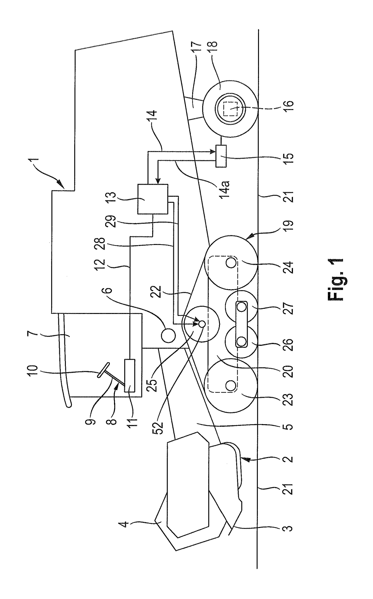
[0035]FIG. 1 depicts a harvesting machine 1 designed as a self-propelled combine harvester. The harvesting machine 1 comprises, on the front thereof, a front harvesting attachment 2 designed as a grain or rapeseed header. This front harvesting attachment 2 is provided, in the working direction thereof, with a cutter bar 3 and with a reel 4, which can be raised and lowered relative to the fr...


PUM


Abstract

A self-propelled harvesting machine includes a front harvesting attachment, a ground drive with first and second drive shafts offset relative to the front harvesting attachment, first and second track roller units to which first and second drive shafts are drivably connected and which extend on both sides of the harvesting machine and a rear axle having rear wheels that are steered via a steering mechanism provided in a rear region of the harvesting machine. The first and second drive shafts are driven by separate first and second hydraulic motors of a hydrostatic transmission. A displacement volume of each of the first and second hydraulic motors is changed depending on a steering movement transferred from the steering mechanism to the rear wheels, realizing an additional moment about a vertical axis of the harvesting machine simultaneously with the steering of the rear wheels.

Description

CROSS-REFERENCE TO A RELATED APPLICATION[0001]The invention described and claimed hereinbelow is also described in German Patent Application DE 10 2014 105 163.7, filed on Apr. 11, 2014. The German Patent Application, the subject matters of which is incorporated herein by reference, provides the basis for a claim of priority of invention under 35 U.S.C. 119(a)-(d).BACKGROUND OF THE INVENTION[0002]The invention relates to a self-propelled harvesting machine comprising a front harvesting attachment and two drive shafts of a ground drive that are offset relative to the front harvesting attachment in the longitudinal direction of the harvesting machine. The drive shafts are drivably connected to track roller units that extend on both sides of the harvesting machine and run in the longitudinal direction thereof. A rear axle having rear wheels steered via a steering mechanism is provided in a rear region of the harvesting machine.[0003]Working machines for earthwork usually comprise a gro...

Claims


Application Information

Patent Timeline
Patent Type & Authority Patents(United States)
IPC IPC(8): B62D11/00A01D41/02A01D41/12B62D11/04A01B69/00B62D11/24
CPCA01B69/007A01D41/02A01D41/12B62D11/04B62D11/24
Inventor BEHRA, JAN PHILIPPLOENEKE, MARKUSBLEISCHWITZ, STEPHAN
Owner CLAAS SELBSTFAHRENDE ERNTEMASCHINEN GMBH
Why Eureka
Try Eureka