
Display device and manufacturing method therefor

a technology of display device and manufacturing method, which is applied in the field of display device, can solve the problems of unfavorable cure of photo-curable resin, and achieve the effect of superior visibility

Active Publication Date: 2017-08-15
PANASONIC INTELLECTUAL PROPERTY MANAGEMENT CO LTD
View PDF14 Cites 1 Cited by
  • Summary
  • Abstract
  • Description
  • Claims
  • Application Information

AI Technical Summary

Benefits of technology

[0006]An object of the present disclosure is to provide a display device in which photo-curable resin is favorably cured and a double reflection of an image is suppressed and that has superior visibility. An object of the present disclosure is to manufacture a display device in which photo-curable resin is favorably cured and a double reflection of an image is suppressed and that has superior visibility.

Problems solved by technology

In this case, when the above thermal adhesive film is used for bonding the cover glass, there is concern that the thermal adhesive film cuts out light of a wavelength with which the photo-curable resin is cured, and the photo-curable resin is not favorably cured.

Method used


Image

  • Display device and manufacturing method therefor
  • Display device and manufacturing method therefor
  • Display device and manufacturing method therefor

Examples


Embodiment Construction

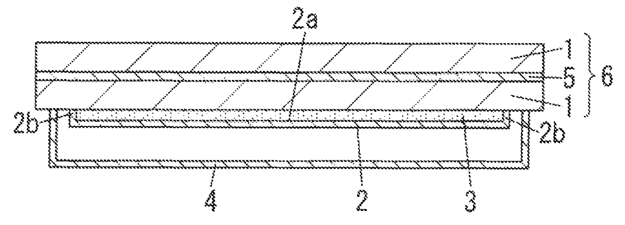
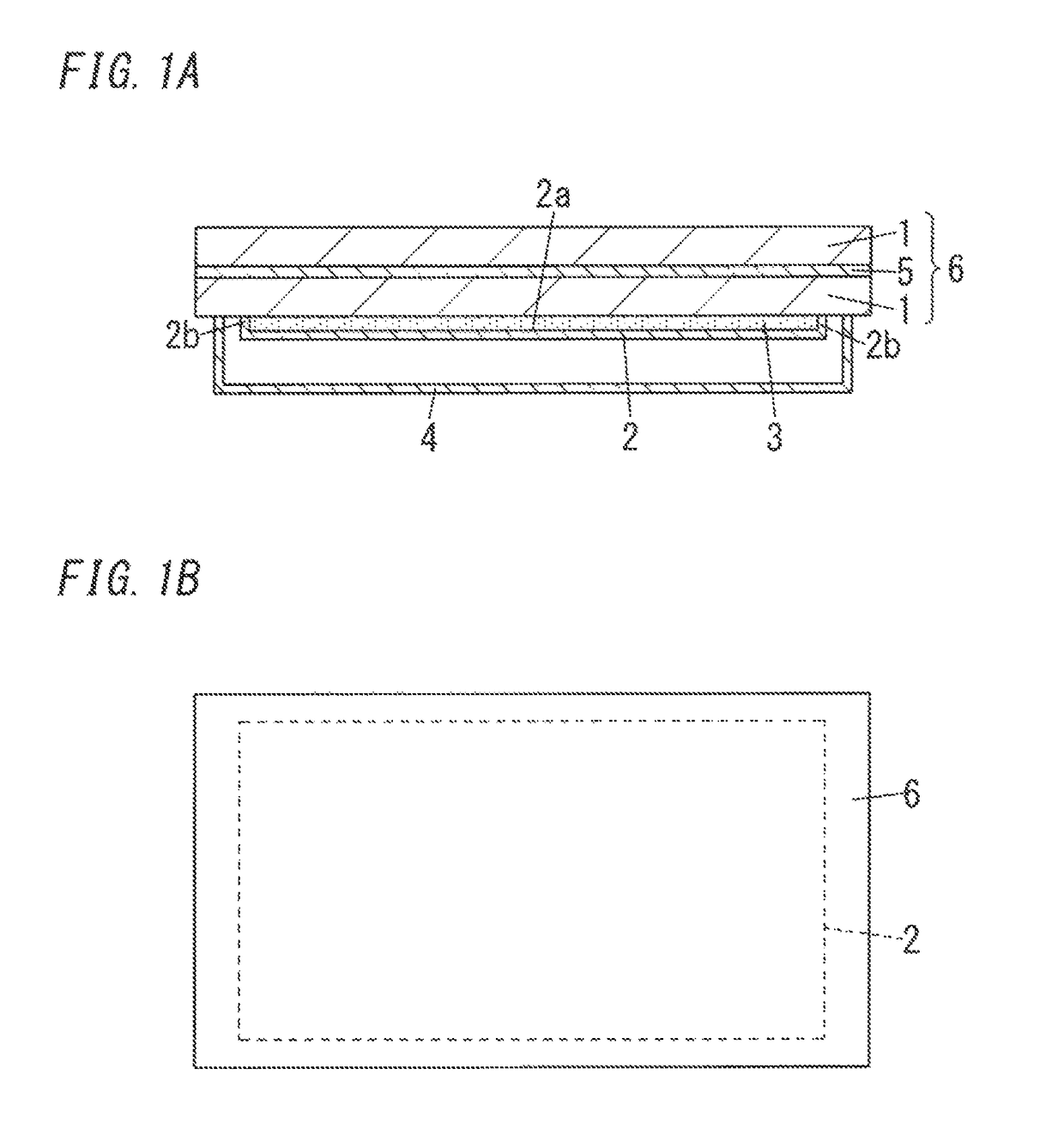
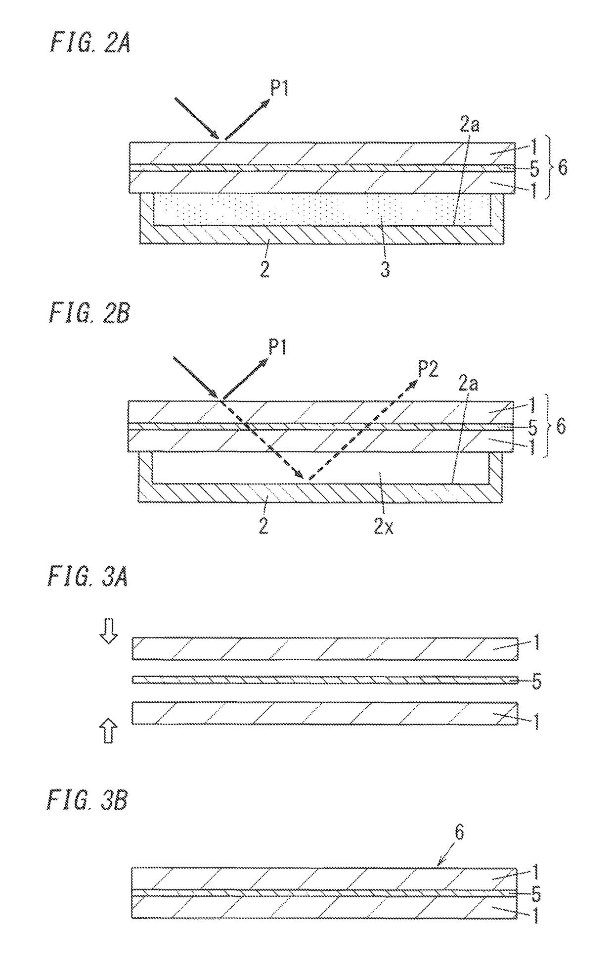
[0022]A display device will be disclosed. The display device includes a transparent laminated body 6, an image-display body 2, and a resin layer 3. The transparent laminated body 6 is formed of two or more transparent substrates 1 that are arranged in layers. The image-display body 2 faces the transparent laminated body 6. The resin layer 3 is disposed between the transparent laminated body 6 and the image-display body 2. The resin layer 3 is made of a photo-curable resin. Two or more transparent substrates 1 are bonded with a thermal adhesive film 5. The thermal adhesive film 5 has optical transmittance of 50% or more at wavelength of 395 nm and optical transmittance of 10% or less at wavelength of 365 nm.

[0023]In the display device, as a result of bonding with the thermal adhesive film 5 having optical transmittance of 50% or more at wavelength of 395 nm, photo-curable resin is favorably cured. As a result of providing a resin layer 3 that is cured photo-curable resin, a double re...


PUM

PropertyMeasurementUnit
optical transmittanceaaaaaaaaaa
peak wavelengthaaaaaaaaaa

Abstract

A display device includes a transparent laminated body 6 formed of transparent substrates 1 that are arranged in layers; an image display body 2 that faces the transparent laminated body 6; and a resin layer 3 that is disposed between the transparent laminated body 6 and the image display body 2 and is made of a photo-curable resin. The transparent substrates 1 are bonded with a thermal adhesive film 5. The thermal adhesive film 5 has optical transmittance of 50% or more at wavelength of 395 nm and optical transmittance of 10% or less at wavelength of 365 nm.

Description

TECHNICAL FIELD[0001]A display device and a manufacturing method therefor will be disclosed. Specifically, display device including a transparent laminated body formed of transparent substrates that are arranged in layers will be disclosed.BACKGROUND ART[0002]Display devices in which a cover glass is placed on a front surface of a display panel are known. As a result of providing the cover glass, the display panel can be protected, and design of display device can be improved.[0003]Strength and safety of display devices have been improved by a cover glass being multi-layered (refer to JP 2010-008450 A, for example). When the cover glass is configured by a so-called laminated glass in which plates of glass are stacked, the strength of the cover glass improves. Also, with such a laminated glass, even when the glass is broken or clacked, scattering of pieces of broken glass can be suppressed by an adhesive that bonds the glass, and as a result safety is improved.[0004]In the cover glas...

Claims


Application Information

Patent Timeline
Patent Type & Authority Patents(United States)
IPC IPC(8): B32B3/00B32B37/18B32B37/12G09F19/22B32B7/12B32B17/06G02F1/1333G02F1/1335
CPCB32B17/064B32B7/12B32B17/06B32B37/1207B32B37/182G02F1/133308G09F19/226B32B2307/412B32B2457/20G02F1/133502G02F2001/133331G02F2202/28G02F1/133331B32B17/10
Inventor URIU, EIICHIHASEGAWA, KENJI
Owner PANASONIC INTELLECTUAL PROPERTY MANAGEMENT CO LTD
Learn More