

Apparatus for controlling load handling device
a technology for handling devices and industrial vehicles, applied in the direction of lifting devices, lifting equipment safety devices, etc., can solve problems affecting the operation stability of forklift trucks, and achieve the effect of reducing the lifting speed and the lifting speed of the load handling devi
- Summary
- Abstract
- Description
- Claims
- Application Information
AI Technical Summary
Benefits of technology
Problems solved by technology
Method used
Image

Examples
first embodiment
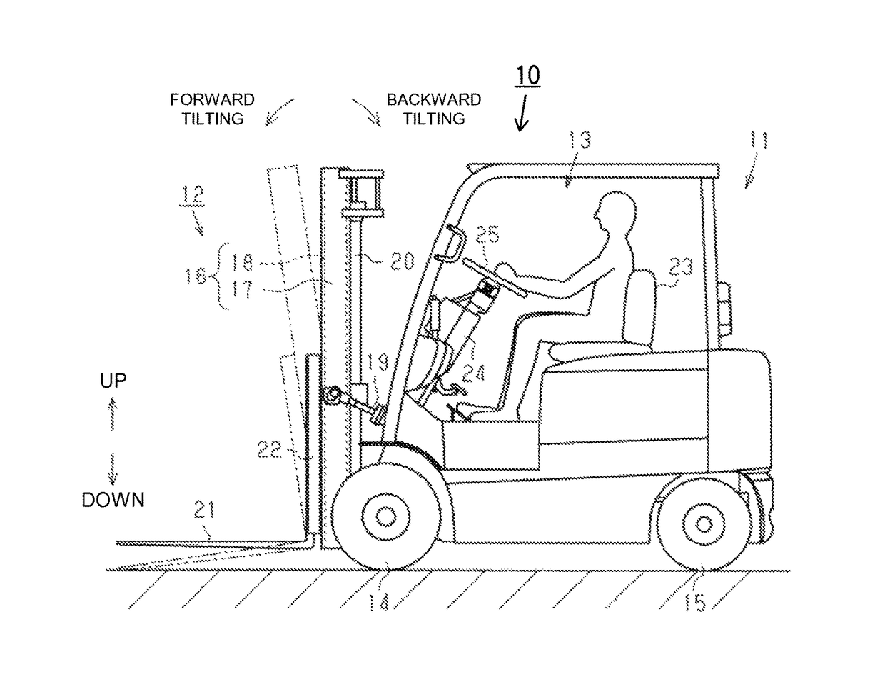
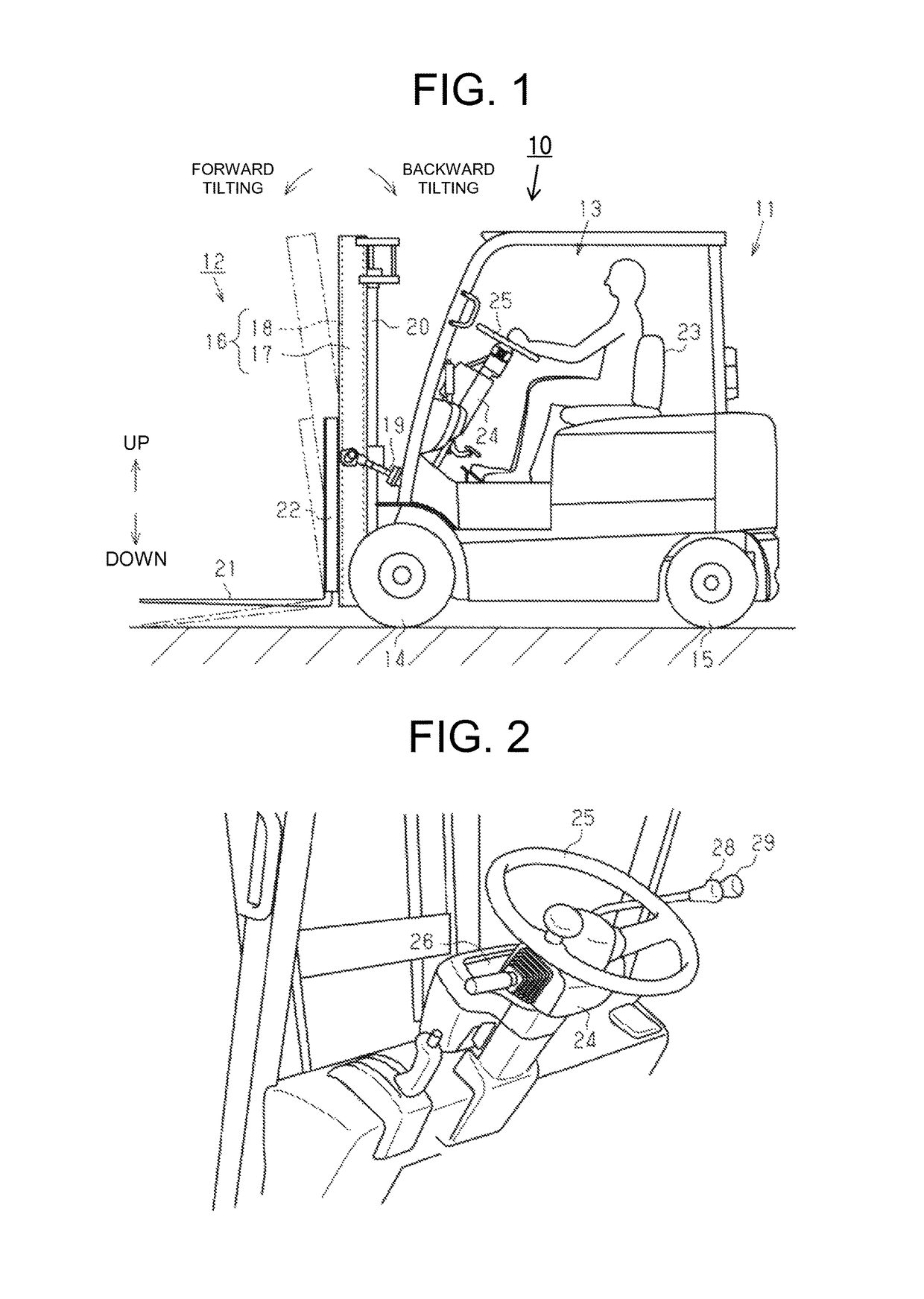
[0017]The following will describe an apparatus for controlling a load handling device according to a first embodiment of the present invention with reference to the accompanying drawings. Referring to FIGS. 1 and 2, the forklift truck as an industrial vehicle of the present invention, which is designated generally by 10, includes a vehicle body 11 and a load handling device 12 installed to the front of the vehicle body 11. The vehicle body 11 has in the center thereof a cabin 13. Drive wheels (front wheels) 14 and steerable wheels (rear wheels) 15 are provided in the front lower part and the rear lower part of the vehicle body 11, respectively. A drive source, such as an engine or a traction motor, is accommodated in the vehicle body 11 and coupled to the drive wheels 14 to drive the drive wheels 14.
[0018]The load handling device 12 includes a mast assembly 16 that is vertically provided at the front of the vehicle body 11. The mast assembly 16 includes a pair of right and left oute...
second embodiment
[0058]The following will describe an apparatus for controlling a load handling device according to a second embodiment of the present invention. In the following description, the parts and elements common to the first embodiment will be denoted with the same numerals or symbols and the description thereof will be omitted.
[0059]As shown in FIG. 6, the vehicle body 11 of the forklift truck 10 is provided with a load sensor 49 that measures or detects a load applied to the forks 21. The load sensor 49 is disposed in a hydraulic circuit provided adjacent to the lower part of the lift cylinder 20. The load sensor 49 detects a hydraulic pressure of hydraulic oil in the lift cylinder 20 and outputs to the control device 41 a detection signal representing the load applied to the forks 21. An example of the load sensor 49 includes a pressure sensor. The CPU 42 of the control device 41 determines that the load is applied to the forks 21 based on the detection signal from the load sensor 49. T...
PUM
 Abstract
Description
Claims
Application Information