Cyclone separator device for gas-oil separation

a technology of gas-oil separation and separator, which is applied in the direction of separation process, filtration separation, auxillary pretreatment, etc., can solve the problems of pressure drop, increase the flow speed, and not provide a satisfactory solution, so as to improve the lift, improve the control of the gas speed, and increase the pressure

Inactive Publication Date: 2013-01-29
MGI COUTIER SA
View PDF6 Cites 18 Cited by
  • Summary
  • Abstract
  • Description
  • Claims
  • Application Information

AI Technical Summary

Benefits of technology

[0030]Other advantageous effects may also be obtained through additional measures.
[0031]According to one of these measures, the body of cylindro-conical overall shape has a larger-diameter upper zone able to cover the upper tangential gas inlet to a greater or lesser extent according to the heightwise position of said body, a relationship thus being established between this heightwise position and the gas inlet cross section for the gases; thus the cross section of the inlet is automatically adapted to suit that of the annular gap. This embodiment therefore affords better control over the speed of the gases by establishing a correlation between the inlet cross section on the one hand, and the restriction in cross section of the variable-width annular gap on the other.
[0032]Advantageously, the annular gap delimited between the conical part of the cylindro-conical body and the wall of the conical oil-recovery zone, has a restriction in cross section at an intermediate point along its height. The restriction in cross section of the annular gap results, for example, from an interior profile that is locally concave, notably in the form of a paraboloid of revolution, of the wall of the conical oil-recovery zone. This restriction in cross section increases the pressure in the gas inlet zone, giving the cylindro-conical body better lift.
[0033]In addition, the shapes of the conical part of said body and of the wall of the conical recovery zone of the cyclone, are advantageously matched to one another in such a way as to obtain an annular gap of a cross section that increases downward, and therefore toward the smaller diameters, so as to obtain a gas speed that remains substantially constant at any height.
[0034]There are various design factors that may influence the speed (that remains substantially constant irrespective of the flow rate) of the gases in the annular gap. In addition to the profile of the conical parts which define this gap, the choice of the weight and therefore of the material of which the cylindro-conical body is made allows for a reduction or increase in speed; a heavier body will lead to a narrower gap, and therefore to a higher speed. Increasing the weight of the body may advantageously be replaced by sprung means, such as a helical compression spring housed in the cylindrical oil-collection zone urging the body with symmetry of revolution downward to bring it into a position of equilibrium. Adjusting the spring stiffness can be used here to influence the speed of the gases.
[0035]Admittedly, U.S. Pat. No. 5,947,300 already discloses a cyclone in which a moving internal body, in the form of a piston, has a spring acting upon it. However, in that document, the spring is used to bring said body into a wide open or closed position; it plays no part in keeping the body in an intermediate position that is a position of equilibrium.

Problems solved by technology

Simply increasing the speed of the flow, particularly for low flow rates, would not provide a satisfactory solution to the problem addressed here because by setting a high speed for low flow rates, notably by reducing the dimensions of the cyclone, a pressure drop would be created that would prove too great for high flow rates.
Conversely, sizing the cyclone in order to limit the pressure drop at high flow rates would yield a cyclone that was even less effective at low flow rates.
However, the sudden variations in cross section would in this case create pressure drops which would restrict the initial energy of the jet of gas.

Method used


Image

  • Cyclone separator device for gas-oil separation
  • Cyclone separator device for gas-oil separation
  • Cyclone separator device for gas-oil separation

Examples


Embodiment Construction

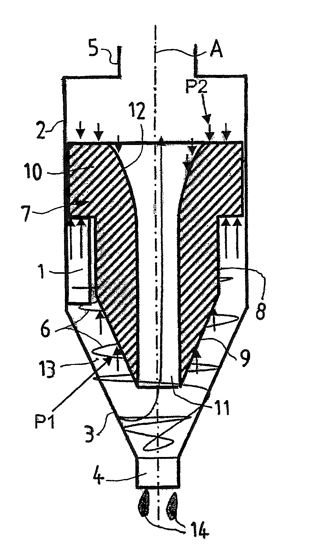
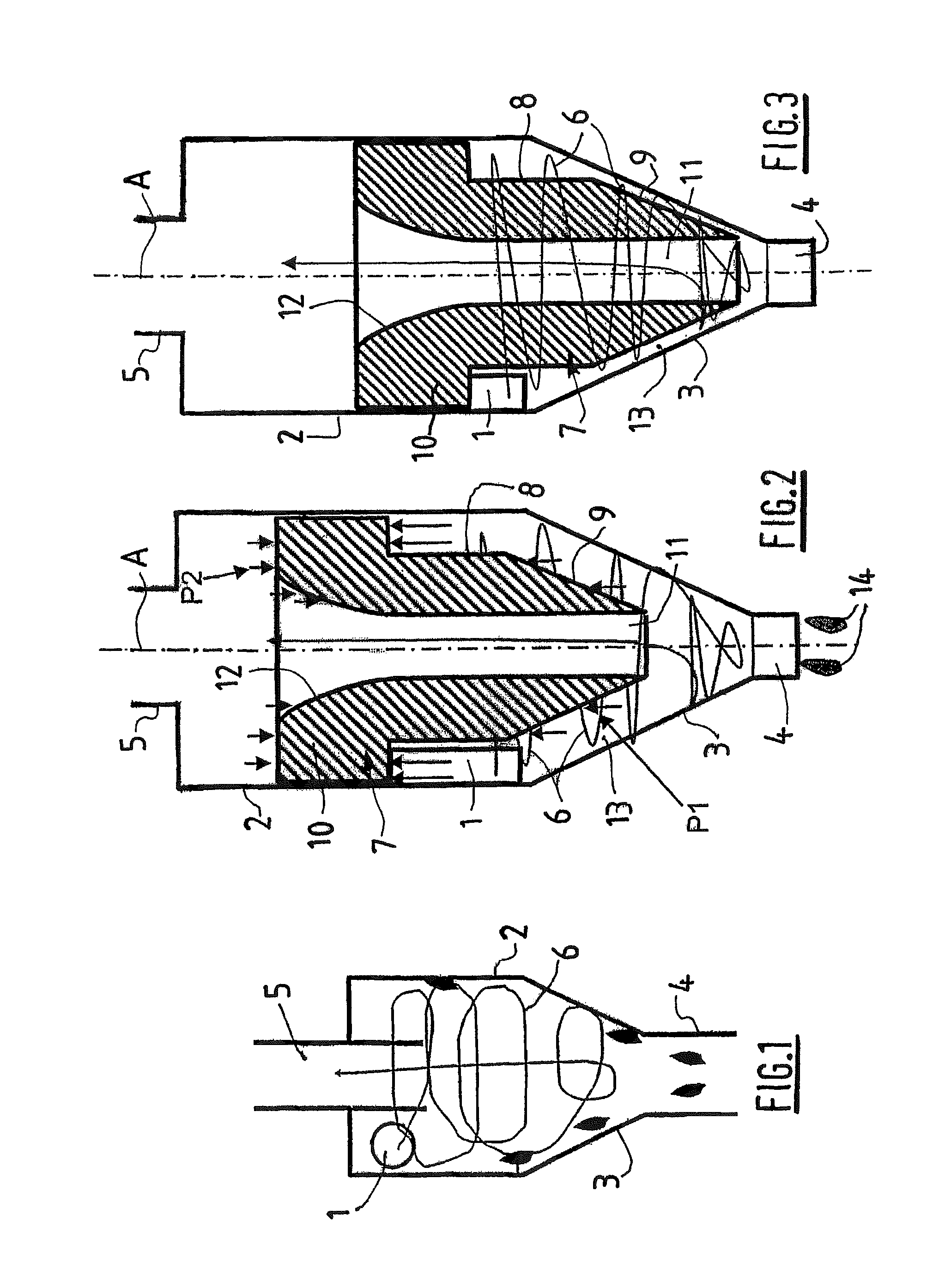
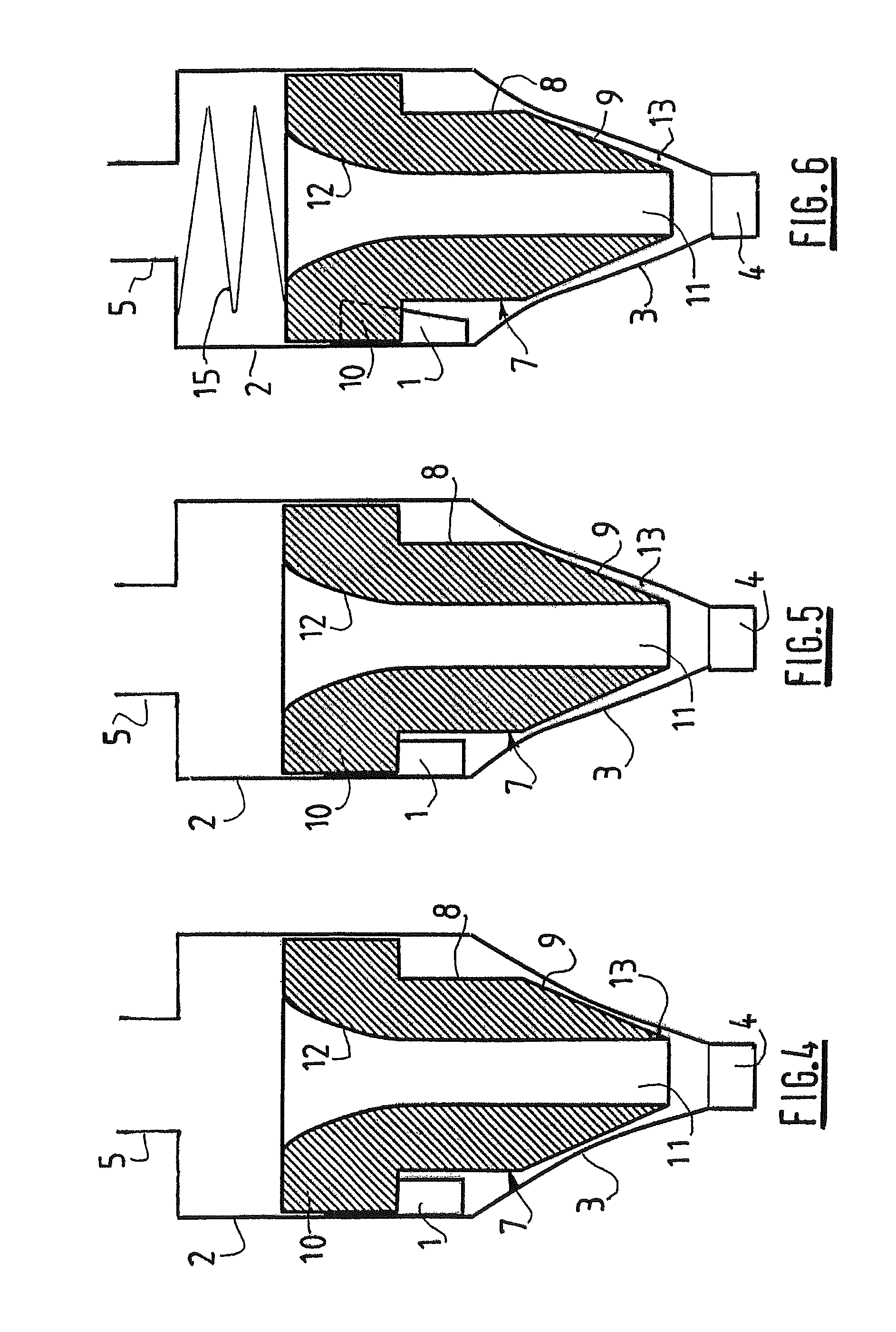
[0045]FIGS. 2 and 3 depict a cyclone separator device the fixed part of which corresponds to the structure of a conventional cyclone and comprises, from top to bottom: an upper tangential inlet 1 for the gases containing the oil that is to be removed, a cylindrical zone 2 for collecting the oil droplets, a conical zone 3 for recovering the oil droplets and a lower oil outlet zone 4. The cyclone also comprises, at its top, an upper axial gas outlet opening 5, to which a suction pipe (not depicted) can be connected.

[0046]A body of revolution 7 of cylindro-conical overall shape is mounted, such that it can move vertically and also such that it is free to turn, inside the cyclone. The body 7 has a cylindrical part 8 situated in register with the cylindrical collection zone 2, and a conical lower part 9 situated in register with the conical recovery zone 3. The body 7 also has a larger-diameter upper zone 10 situated at the level of the upper tangential inlet 1. The body 7 is pierced ver...


PUM

PropertyMeasurementUnit
flow rateaaaaaaaaaa
speedaaaaaaaaaa
symmetryaaaaaaaaaa

Abstract

This cyclone device performs diphasic gas-oil separation to remove oil from the recirculated crank cases of an internal combustion engine. Mounted such that it can move vertically inside the cyclone is a body (7) exhibiting symmetry of revolution, particularly one of cylindro-conical overall shape. The body (7) delimits, with the walls of the cylindrical collecting zone (2) and/or of the conical zone (3) for recuperating the liquid oil, an annular gap (13) such that the passage cross section can vary according to the self-adjusting heightwise position of the body (7), as a function of the gas flow rate. The speed of the gases thus remains constant for variable gas flow rates.

Description

TECHNICAL FIELD[0001]The invention relates in general to separator devices of the kind known under the heading of “cyclone” separators. More specifically, this invention applies to a cyclone separator device intended for diphasic gas-oil separation in an internal combustion engine, and more specifically still, to a separator designed to separate and recover liquid oil particles contained in the recirculated crank case gases of an internal combustion engine, notably of a motor vehicle.BACKGROUND[0002]Devices, also known as “oil separators” or “oil traps” already exist and are incorporated into the cylinder head cover of an internal combustion engine and comprise, firstly, means designed to remove the liquid oil that enters the cylinder head cover and, secondly, means designed to remove oil droplets or particles from the crank case gases.[0003]In order to carry out this diphasic gas-oil separation, it is possible to plan on using a cyclone, which exploits the inertia of the oil drople...

Claims


Application Information

Patent Timeline
Patent Type & Authority Patents(United States)
IPC IPC(8): B01D47/00
CPCB01D45/16B04C5/04B04C5/13B04C5/103F01M2013/0422F01M2013/0427
Inventor GUERRY, PASCALNOLLEVAUX, ANTONYFOHRER, THIERRYMARTINENGO, HERVE
Owner MGI COUTIER SA
Why Eureka
Try Eureka