Electronically controlled internal damper

a technology of internal damper and electric control, which is applied in the direction of liquid based dampers, shock absorbers, vibration suppression adjustments, etc., can solve the problems of large degree of freedom, difference in damping force, and inability of electric control external dampers to independently adjust damping forces, etc., to achieve simple structure, reduce rigidity, and increase sealing performance

Active Publication Date: 2017-08-15
HL MANDO CORP
View PDF6 Cites 2 Cited by
  • Summary
  • Abstract
  • Description
  • Claims
  • Application Information

AI Technical Summary

Benefits of technology

[0012]The present invention has been made in an effort to solve the above problems and is directed to provide an electronically controlled internal damper that is capable of implementing damping performance in both a soft mode and a hard mode through a relatively simple structure and increasing sealing performance while reducing rigidity, thereby increasing a degree of freedom of damping force adjustment and a variable range by reducing a damping force of a soft mode and maintaining a damping force of a hard mode.

Problems solved by technology

Consequently, the electronically controlled external damper cannot independently adjust the damping forces of the rebound stroke and the compression stroke in the valve, wherein a difference in the damping force occurs depending on the difference in a flow rate passing through the same valve.
In consideration of these points, it is possible to adjust the damping force of the compression stroke through a rigidity of a check valve on a compression side of a main piston, but its degree of freedom is considerably limited as compared with a conventional damper that adjusts a damping force by using a separate valve in each stroke.
Therefore, even though the electronically controlled damper is expensive as compared with the conventional damper, the degree of freedom of damping force adjustment decreases.

Method used


Image

  • Electronically controlled internal damper
  • Electronically controlled internal damper
  • Electronically controlled internal damper

Examples


Embodiment Construction

[0018]The advantages and features of the present invention and methods for achieving them will become more apparent from the following embodiments that are described in detail in conjunction with the accompanying drawings.

[0019]However, the present invention is not limited to the following embodiments, but may be embodied in various forms.

[0020]These embodiments are provided so that this disclosure will be thorough and complete, and will fully convey the scope of the invention to those skilled in the art.

[0021]The scope of the present invention is defined by the appended claims.

[0022]Therefore, in some embodiments, detailed descriptions of well-known elements, operations, and technologies will be omitted for simplicity and clarity.

[0023]Throughout the disclosure, like reference numerals refer to like elements. The terminology used herein is intended to just describe particular embodiments and is not intended to limit the present invention.

[0024]In this specification, the singular fo...


PUM


Abstract

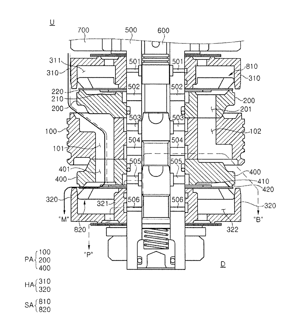
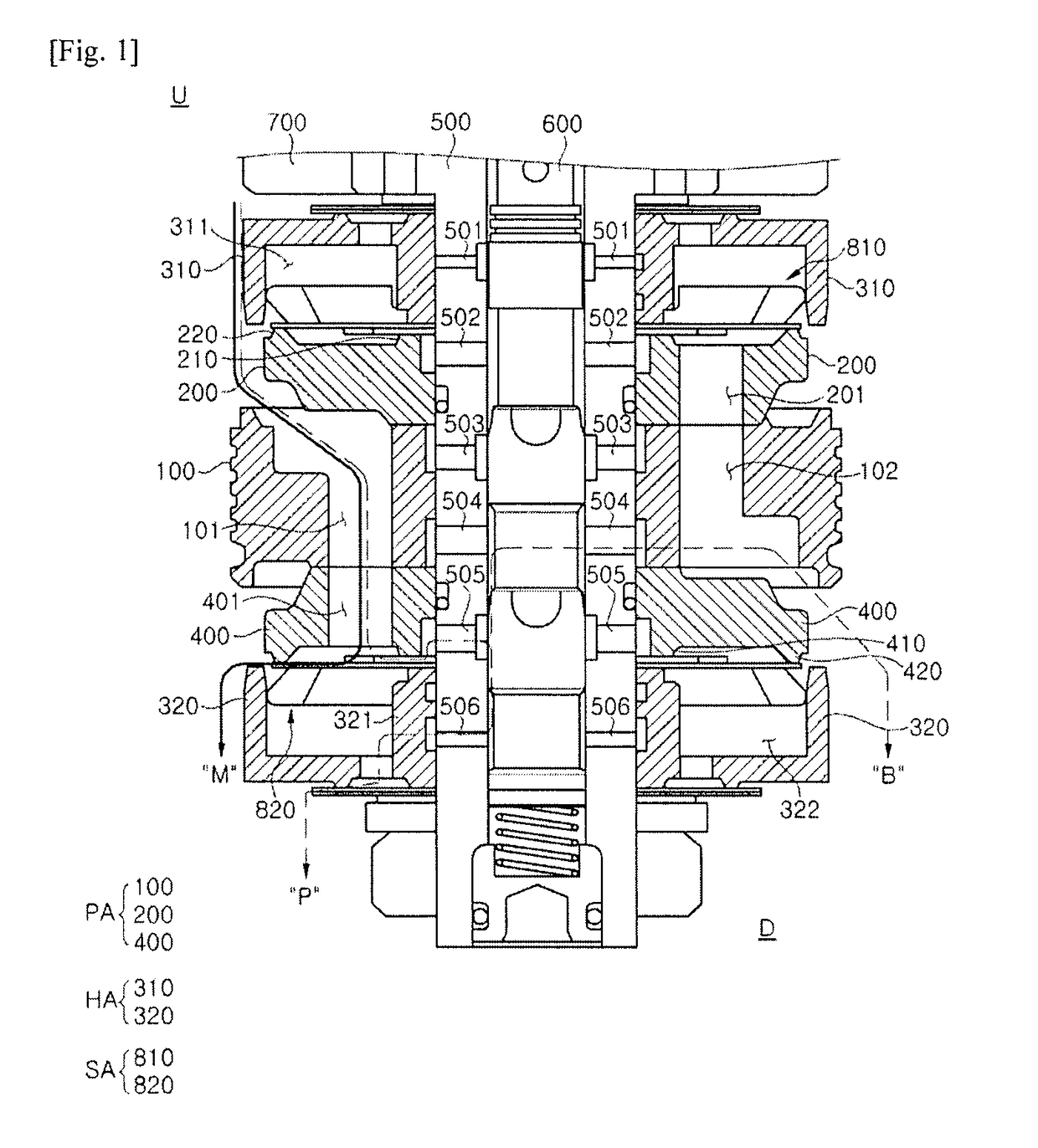
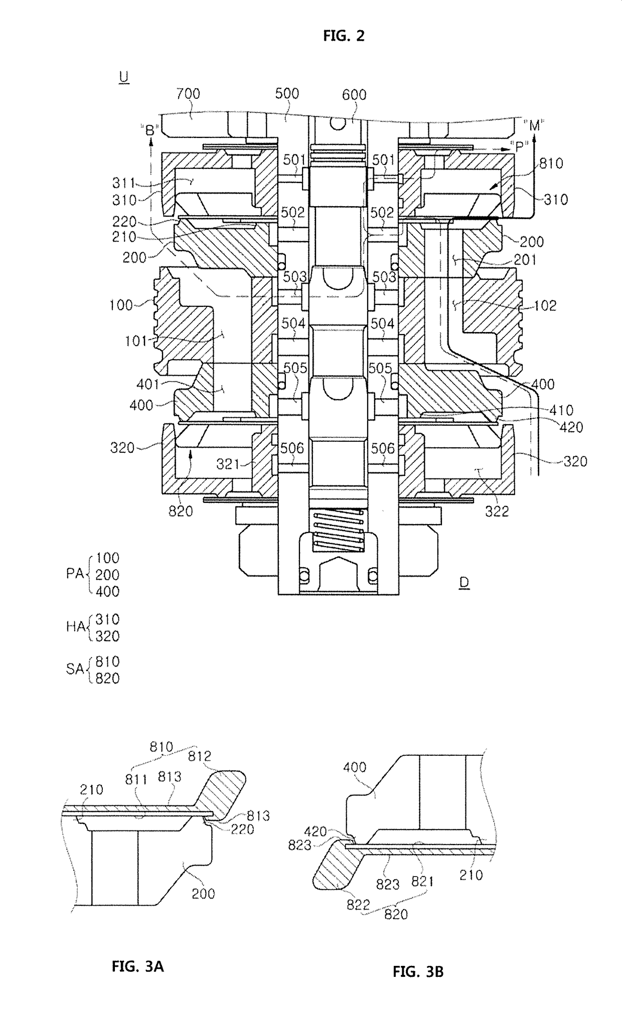
An electronically controlled internal damper includes: a main passage formed by a working fluid flowing through a main piston; a pilot passage formed by a working fluid as much as a predetermined amount discharged from a first pilot chamber and a second pilot chamber so as to maintain internal pressures of the first pilot chamber and the second pilot chamber to a predetermined level when pressures of the first pilot chamber and the second pilot chamber are increased beyond the predetermined level; and a bypass passage formed by a working fluid passing through the compression retainer and the rebound retainer symmetrically disposed above and under the main piston and a plurality of holes formed transversely to a vertical length direction of a spool rod. Accordingly, the electronically controlled internal damper is capable of implementing damping performance in both a soft mode and a hard mode with a relatively simple structure and increasing sealing performance while reducing rigidity.

Description

CROSS-REFERENCE(S) TO RELATED APPLICATION[0001]This application claims priority of Korean Patent Application No. 10-2015-0014406, filed on Jan. 29, 2015, in the Korean Intellectual Property Office, which is hereby incorporated by reference in its entirety.BACKGROUND OF THE INVENTION[0002]Field of the Invention[0003]The present invention relates to an electronically controlled internal damper, and more particularly, to an electronically controlled internal damper that is capable of implementing damping performance in both a soft mode and a hard mode through a relatively simple structure and increasing sealing performance while reducing rigidity.[0004]Description of the Related Art[0005]Generally, in an electronically controlled external damper, since a passage of a rebound stroke is the same as a passage of a compression stroke, damping forces of the rebound stroke and the compression stroke is adjusted through one variable valve.[0006]Consequently, the electronically controlled exte...

Claims


Application Information

Patent Timeline
Patent Type & Authority Patents(United States)
IPC IPC(8): F16F9/46F16F9/516F16F9/16F16F9/32F16F9/348
CPCF16F9/348F16F9/5165F16F9/16F16F9/3214F16F9/3484F16F9/464F16F9/465F16F9/3207F16F15/023F16F9/3415F16F9/466F16F9/5123
Inventor KIM, EUN JOONG
Owner HL MANDO CORP
Why Eureka
Try Eureka