Optical transmitter and control method of optical transmitter

a control method and optical transmitter technology, applied in electromagnetic transmission, electrical equipment, transmission, etc., can solve the problems of long time and difficulty in determining whether the output light beam of each of the first and second mach-zehnder optical modulators is in the extinction sta

Active Publication Date: 2017-08-15
MITSUBISHI ELECTRIC CORP
View PDF10 Cites 4 Cited by
  • Summary
  • Abstract
  • Description
  • Claims
  • Application Information

AI Technical Summary

Benefits of technology

[0006]An object of the present invention is to provide an optical transmitter capable of determining initial values of respective bias voltages to be applied to two modulators in a short time, and a control method of the optical transmitter.

Problems solved by technology

Therefore, it is difficult to determine whether the output light beam from each of the first and second mach-zehnder optical modulators is in the extinction state.
Accordingly, there is a problem that it takes a long time.

Method used


Image

  • Optical transmitter and control method of optical transmitter
  • Optical transmitter and control method of optical transmitter
  • Optical transmitter and control method of optical transmitter

Examples


first preferred embodiment

[0019]

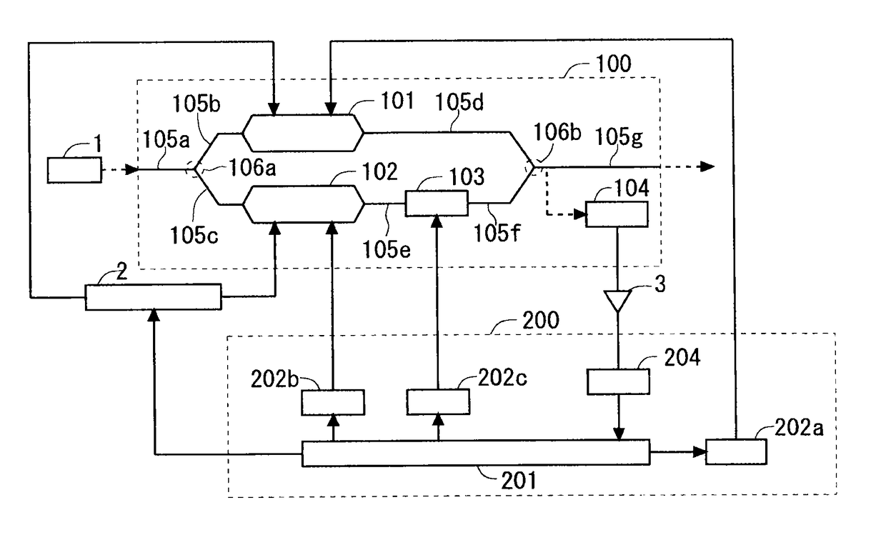
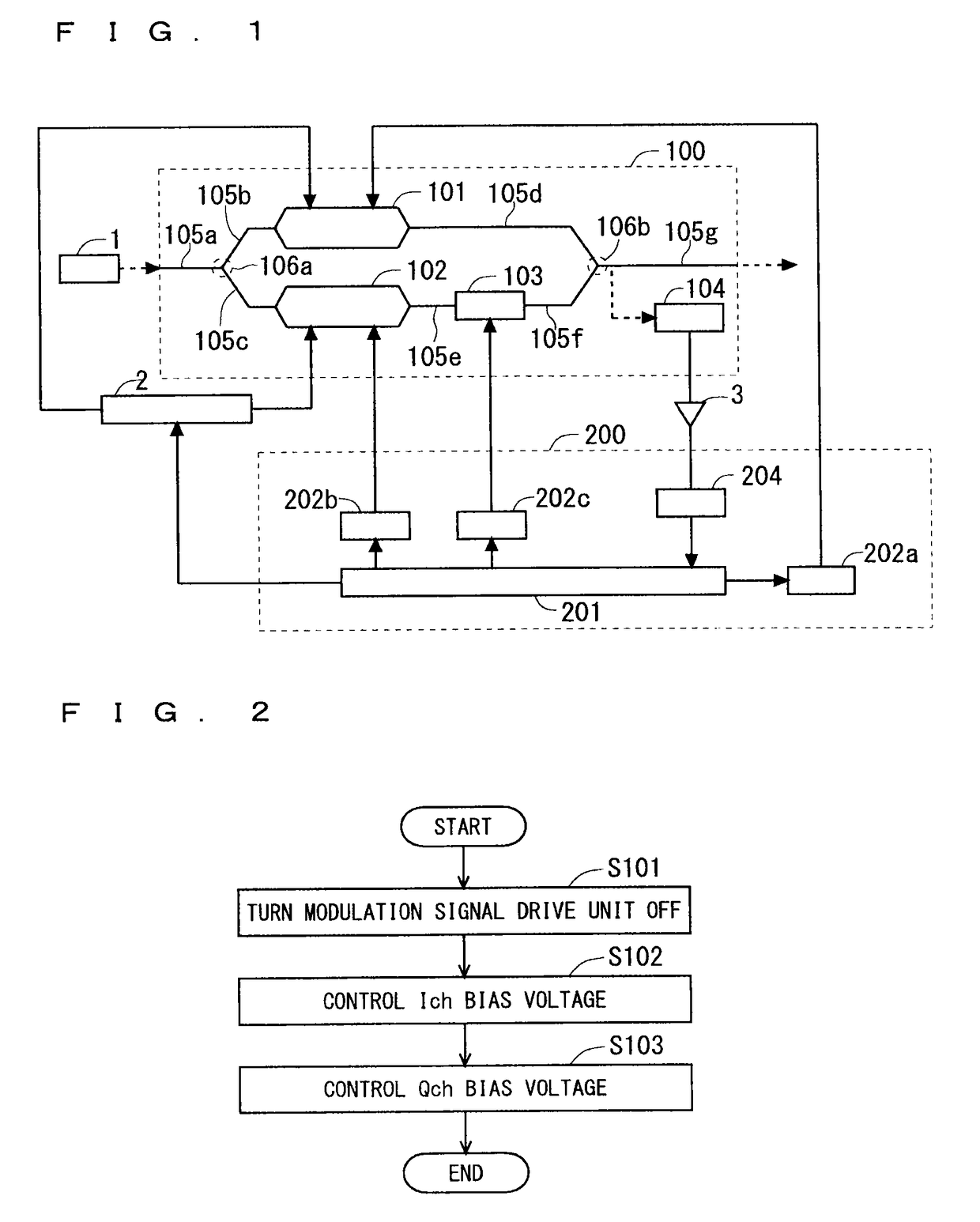
[0020]FIG. 1 is a function block diagram of an optical transmitter according to this preferred embodiment. The optical transmitter according to this preferred embodiment includes an optical modulation unit 100 that modulates a beam incident from a light source 1, based on an input modulation signal and an input bias voltage, a modulation signal drive unit 2 that inputs the modulation signal to the optical modulation unit 100, and a controller 200 that controls operation of the optical modulation unit 100 and the modulation signal drive unit 2. The light source 1 and the optical modulation unit 100 are optically connected by, for example, an optical fiber.

[0021]The optical modulation unit 100 includes a first optical modulator 101, a second optical modulator 102, and an optical phase regulator 103. The first and second optical modulators 101 and 102, and the optical phase regulator 103 are formed in a substrate containing, for example, lithium niobate. Additionally, on the subs...

second preferred embodiment

[0065]

[0066]The optical transmitter according to the first preferred embodiment monitors the output of the optical modulation unit 100 in an initial state where no modulation signal is input to the optical modulation unit 100, and searches for the initial bias voltages of the first and second optical modulators 101 and 102 such that the light beam output from the optical modulation unit 100 is brought into the most extinction state. An optical transmitter according to this preferred embodiment searches initial values (initial bias voltages Vi and Vq) of an Ich bias voltage and a Qch bias voltage such that a light beam output from an optical modulation unit 100 is brought into the most extinction state, in an initial state where no modulation signal is input to the optical modulation unit 100, similarly to the first preferred embodiment.

[0067]FIG. 6 is a function block diagram of the optical transmitter according to this preferred embodiment. The optical transmitter according to this...

third preferred embodiment

[0076]

[0077]The optical transmitter according to each of the first preferred embodiment and the second preferred embodiment monitors the output of the optical modulation unit 100 in an initial state where no modulation signal is input to the optical modulation unit 100, and searches for the initial bias voltages Vi and Vq of the first and second optical modulators 101 and 102 such that the light beam output from the optical modulation unit 100 is brought into the most extinction state.

[0078]An optical transmitter according to this preferred embodiment searches for initial bias voltages Vi and Vq such that a light beam output from an optical modulation unit 100 is brought into the most extinction state, in an initial state where no modulation signal is input to the optical modulation unit 100, similarly to the first preferred embodiment and the second preferred embodiment. This preferred embodiment is different from the first preferred embodiment and the second preferred embodiment i...


PUM


Abstract

An optical modulation unit included in an optical transmitter includes two optical modulators that modulate each of two light beams based on applied bias voltages and input modulation signals, and an optical phase regulator that is connected to either of the two optical modulators, and regulates a phase of the light beam incident on the optical modulator. In a state where no modulation signal is input to the two optical modulators, while keeping bias voltages to be applied to one optical modulator and the optical phase regulator constant, the controller determines a first initial bias voltage such that an output light beam from the other optical modulator becomes zero. Thereafter, the controller determines a second initial bias voltage such that an output light beam from the one optical modulator becomes zero, while applying the first initial bias voltage to the other optical modulator.

Description

BACKGROUND OF THE INVENTION[0001]Field of the Invention[0002]The invention relates to an optical transmitter, and a control method of an optical transmitter, and more particularly to an optical transmitter including an optical modulation unit that modulates an incident light beam, a modulation signal drive unit that inputs a modulation signal to the optical modulation unit, a controller that controls the optical modulation unit and the modulation signal drive unit.[0003]Description of the Background Art[0004]It is known that the optimum bias voltage of an MZ (Mach-Zehnder) optical modulator drifts by temperature or aging change. Therefore, in order to keep the quality of a transmission optical signal, control for making a bias voltage to follow an optimum bias value is performed. For example, in an optical transmitter that performs ABC (automatic bias control) of an I / Q modulator, there is known an optical transmitter that controls three bias voltages, I-ch, Q-ch, and Phase in turn ...

Claims


Application Information

Patent Timeline
Patent Type & Authority Patents(United States)
IPC IPC(8): H04B10/00H04B10/50
CPCH04B10/50575H04B10/5053
Inventor ENOKI, KENTAROSHIMAKURA, YASUHISAYAGYU, EIJISHINTAKU, HIROAKIHAYASHI, SHUSAKU
Owner MITSUBISHI ELECTRIC CORP
Why Eureka
Try Eureka