Fiber scaffolds for use creating implantable structures

a fiber scaffold and implantable technology, applied in the field of fiber scaffolds for creating implantable structures, can solve the problems of thrombosis at needle perforation, present blood vessels that are not viable, and shredding of the graft wall

Active Publication Date: 2017-08-22
NFS IP HLDG LLC
View PDF83 Cites 42 Cited by
  • Summary
  • Abstract
  • Description
  • Claims
  • Application Information

AI Technical Summary

Problems solved by technology

However, due to underlying diseases in late stages, many patients present blood vessels that are non-viable for creation of a native AV fistula.
Other complications include formation of pseudo-aneurysms in the graft (dilations), shredding of the graft wall due to repeated needle perforations, and thrombosis at needle perforations that do not close after needle removal.
Secondarily, venous or arterial neo-intimal hyperplasia occurs due to the fact that the currently used ePTFE grafts are perceived by the host as a foreign body, eliciting an exuberant foreign body inflammatory response at the site of anastomosis, eventually resulting in hyperproliferation of cells that deposit undesirable tissue in the lumen of the graft or vein / artery at the anastomosis site or just downstream from the venous anastomosis location.
In addition, current ePTFE conduits do not address compliance mismatch issues on the artery or venous side and clinicians point to this being another source of biological / biomechanical mismatch that results in hyperplastic response that leads to reduced patency rates.
Finally, needle access sites in ePTFE grafts for dialysis are commonly reported sites for graft failures which can range from lack of closure / healing, blood stream and graft site infection, formation of pseudo aneurysms, and destruction of the graft wall due to multiple perforations, all of which require graft removal and replacement.
These problems occur primarily due to two reasons: (1) inability of ePTFE conduits to self-close needle perforation site, and (2) inability of ePTFE conduits to produce biologic healing at needle perforation sites.
However, the inability of the synthetic ePTFE graft to go through a normal wound healing process, similar to what happens during vascular access at a venous or arterial site is a huge drawback.
Since current grafts do not allow for effective cellular infiltration, angiogenesis, and tissue integration, they function primarily as a passive conduit and are susceptible to perforation related pin holing failures.

Method used


Image

  • Fiber scaffolds for use creating implantable structures
  • Fiber scaffolds for use creating implantable structures
  • Fiber scaffolds for use creating implantable structures

Examples


Embodiment Construction

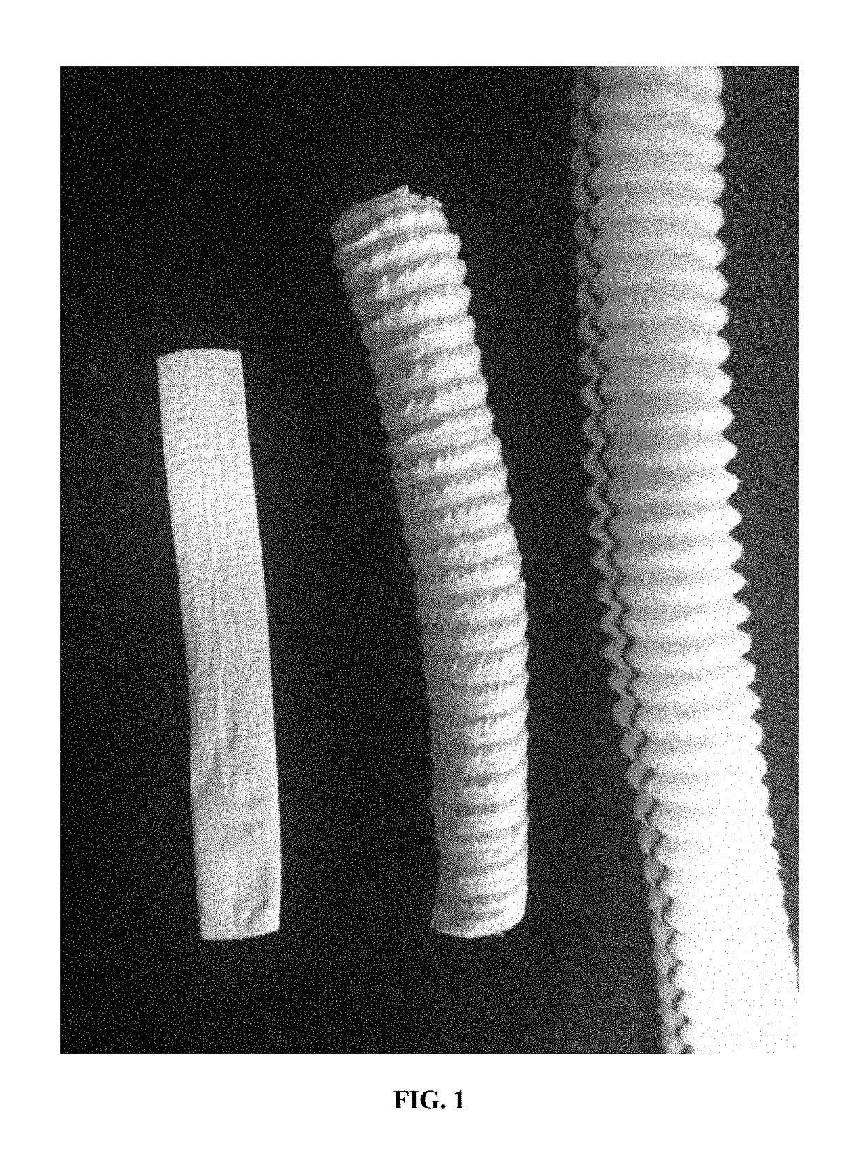
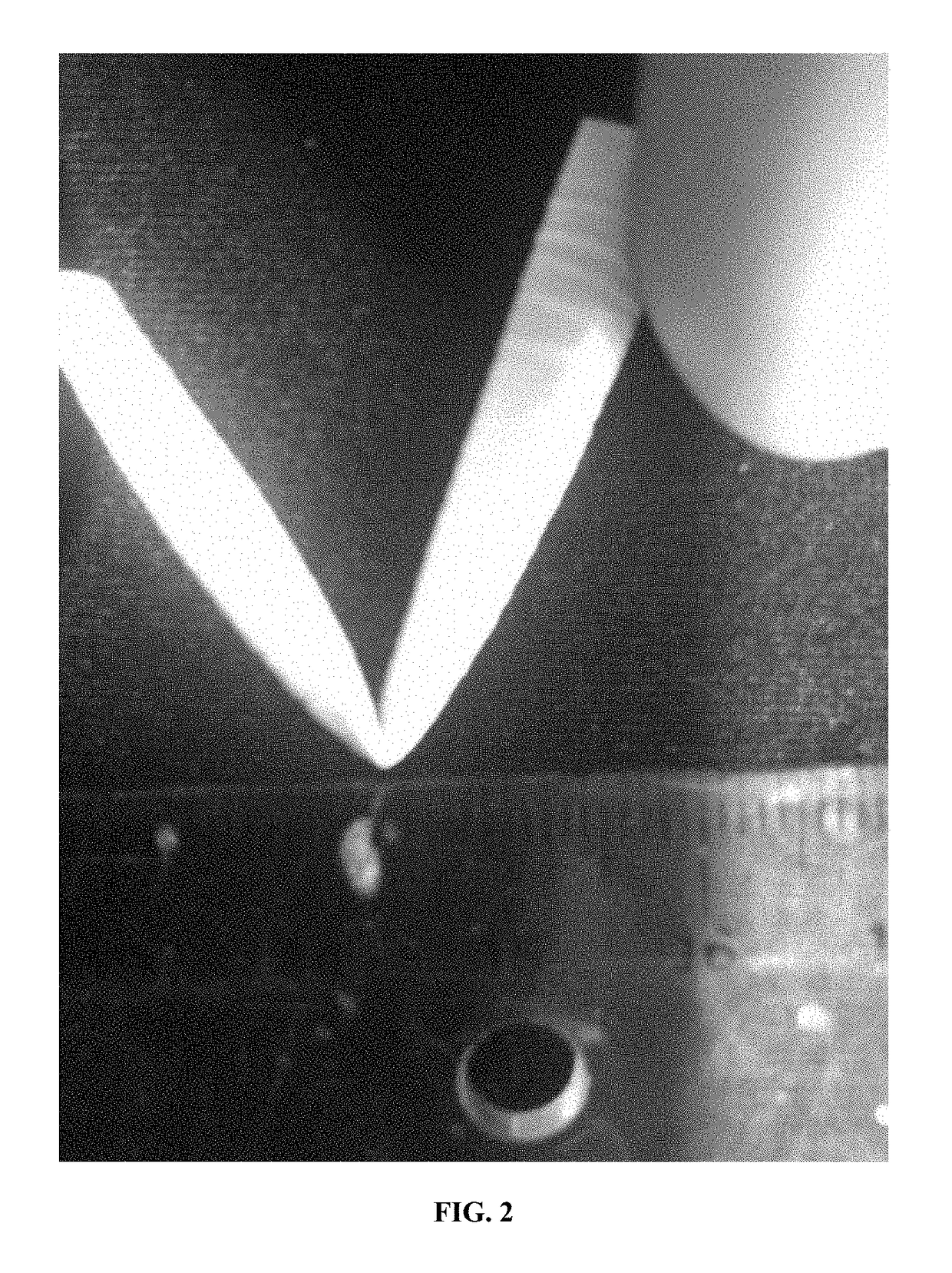
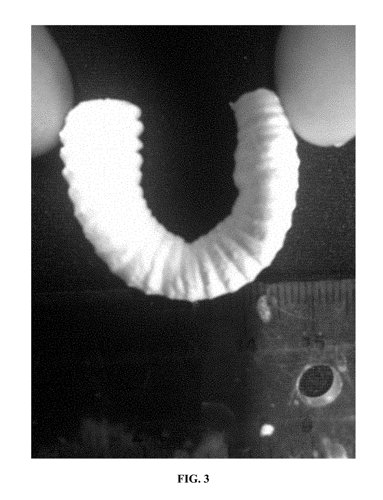
[0022]Exemplary embodiments of the present invention are now described with reference to the Figures. Although the following detailed description contains many specifics for purposes of illustration, a person of ordinary skill in the art will appreciate that many variations and alterations to the following details are within the scope of the invention. Accordingly, the following embodiments of the invention are set forth without any loss of generality to, and without imposing limitations upon, the claimed invention.

[0023]With reference generally to the Figures, the present invention involves the development and construction of implantable artificial organs and tissues for humans and / or animals, and more specifically to a process or method for manufacturing two and three-dimensional polymer microscale and nanoscale structures for use as scaffolds in the growth of biological structures such as hollow organs, luminal structures, and / or other structures within the body. The use of these...


PUM

PropertyMeasurementUnit
pore sizeaaaaaaaaaa
diameteraaaaaaaaaa
porositiesaaaaaaaaaa

Abstract

A synthetic construct suitable for implantation into a biological organism that includes at least one polymer scaffold; wherein the at least one polymer scaffold includes at least one layer of polymer fibers that have been deposited by electrospinning; wherein the orientation of the fibers in the at least one polymer scaffold relative to one another is generally parallel, random, or both; and wherein the at least one polymer scaffold has been adapted to function as at least one of a substantially two-dimensional implantable structure and a substantially three-dimensional implantable tubular structure.

Description

CROSS-REFERENCE TO RELATED APPLICATIONS[0001]This patent application claims the benefit of U.S. Provisional Patent Application Ser. No. 61 / 882,504 filed on Sep. 25, 2013, and entitled “Fiber Scaffolds for Use in Arteriovenus Shunts and Vascular Grafts”, the disclosure of which is hereby incorporated by reference herein in its entirety and made part of the present U.S. utility patent application for all purposes.BACKGROUND OF THE INVENTION[0002]Tissue engineering typically involves the synthesis of biologically relevant tissue for a wide range of applications including the replacement or support of damaged organs. A common strategy is culturing target specific cells in vitro in a scaffold followed by implantation of the scaffold into a biological organism. As a logical cellular source for tissue engineering, stem cells have attracted a great deal of attention due to their relatively fast rate of proliferation and diverse differentiation potential for various phenotypes. These include...

Claims


Application Information

Patent Timeline
Patent Type & Authority Patents(United States)
IPC IPC(8): A61L27/18A61L27/38A61L27/54A61L31/14A61L31/16A61L27/50A61L31/04A61L27/14A61L27/20A61L27/58A61L27/26
CPCA61L27/18A61L27/14A61L27/20A61L27/26A61L27/38A61L27/3804A61L27/507A61L27/54A61L27/58A61L31/04A61L31/14A61L31/148A61L31/16A61L2300/406A61L2300/41A61L2300/412A61L2300/414A61L2300/416A61L2300/64A61L2400/12A61L2430/02A61L2430/20A61L2430/34Y10T428/249947
Inventor JOHNSON, JED K.KAYUHA, ROSS
Owner NFS IP HLDG LLC
Why Eureka
Try Eureka