Water filter cartridge with slanted nozzles

a technology of water filter cartridges and nozzles, which is applied in the direction of lighting and heating apparatus, domestic cooling apparatus, and separation processes, etc., can solve the problems of filter cartridges that are difficult to extract from the manifold and the retaining mechanism, and achieve the effects of facilitating ice removal, facilitating breakage and removal, and facilitating dislodging i

Active Publication Date: 2017-08-22
TST WATER INC
View PDF16 Cites 0 Cited by
  • Summary
  • Abstract
  • Description
  • Claims
  • Application Information

AI Technical Summary

Benefits of technology

[0006]A water filter cartridge has an end cap with separate inlet and outlet nozzles connected to the end of a cylindrical tube that extends from the end cap. The nozzles are slanted and offset either laterally from the longitudinal axis of the tube to which they are mounted or offset vertically from the end of the tube to which they are mounted. Illustrated embodiments are disclosed with the nozzles slanted at angles of about 5°, about 20° and about 16°, with lateral offsets of about 0.01 to 0.1 inches and vertical offsets of about 0.02-0.05 inches. The slanted nozzles may have a cylindrical outer surface sized, located and oriented to actuate valves in a mating manifold, or the nozzles may have a longitudinal ridge on the outside of the nozzle forms a cam that actuates valves in a mating manifold. The slanted nozzles may have a conical outer surface located to actuate the valves or they may have a cam extending from the outer surface of the nozzles to actuate the valves. The water passage in the nozzles is conical, expanding toward the nozzle end and opening onto a portion of the nozzle side to form a sharper, distal tip adjacent an end of the cam. Expanding ice pushes itself out of the conical passage and facilitates ice removal. The narrow end of the conical passage facilitates breakage and removal of ice from the nozzle. The slanted orientation of the nozzle tip and when present the ridged cam both provide an irregular surface that facilitates dislodging ice from the manifold port into which the nozzles are inserted during use. The slanted nozzle orientation directs water toward a corner end of the port in the manifold into which the nozzle is inserted during use and the directed flow is believed to help remove ice from the corners.

Problems solved by technology

One difficulty with the above filter cartridges is that occasionally the water in the manifold becomes cold enough to freeze and then the filter cartridge is difficult to extract from the manifold and from the retaining mechanism.
But even with the removal achieved users typically want to quickly clear the ice from the inlet or outlet and immediately reinsert the filter cartridge for use and the current nozzle and manifold designs make that difficult.

Method used


Image

  • Water filter cartridge with slanted nozzles
  • Water filter cartridge with slanted nozzles
  • Water filter cartridge with slanted nozzles

Examples


Embodiment Construction

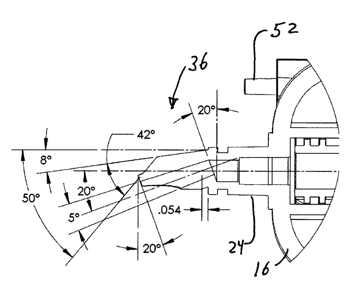
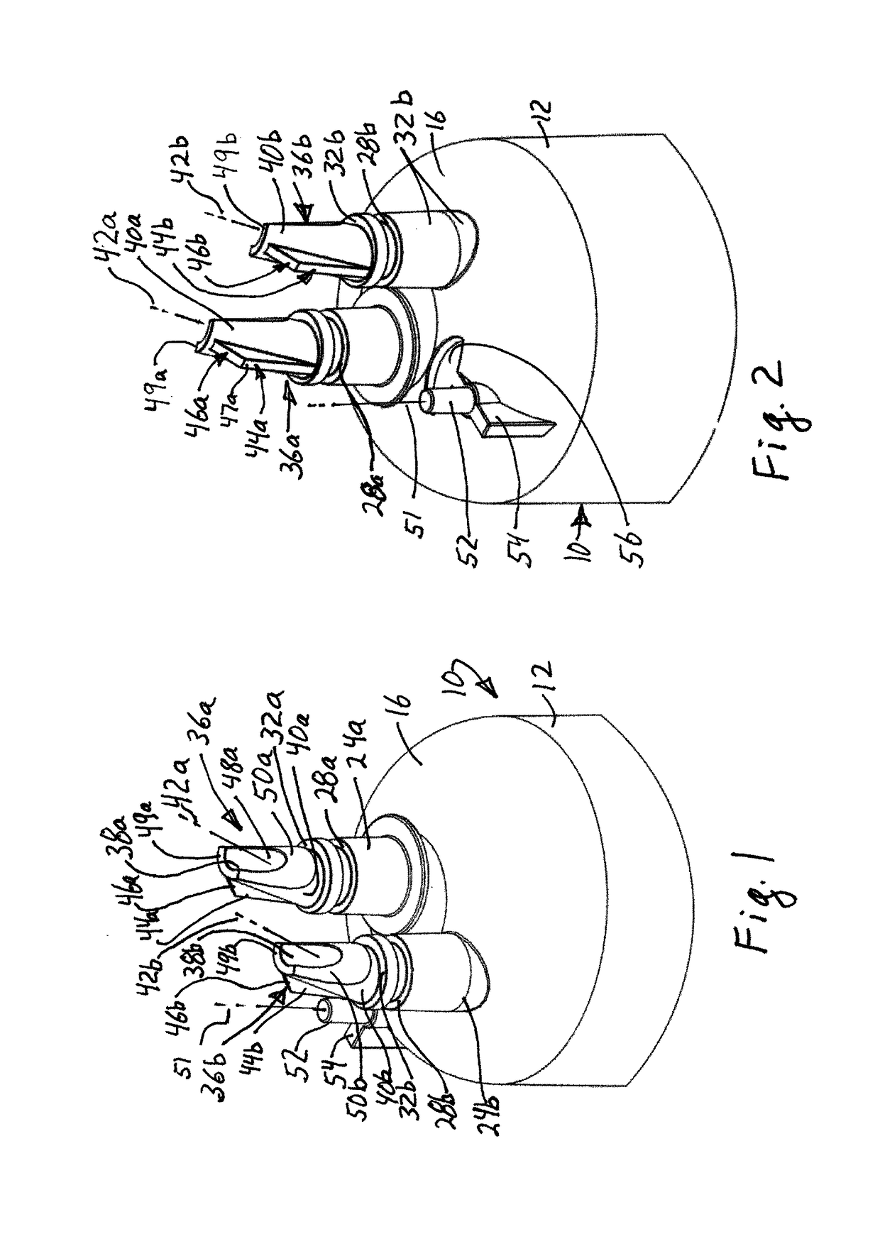
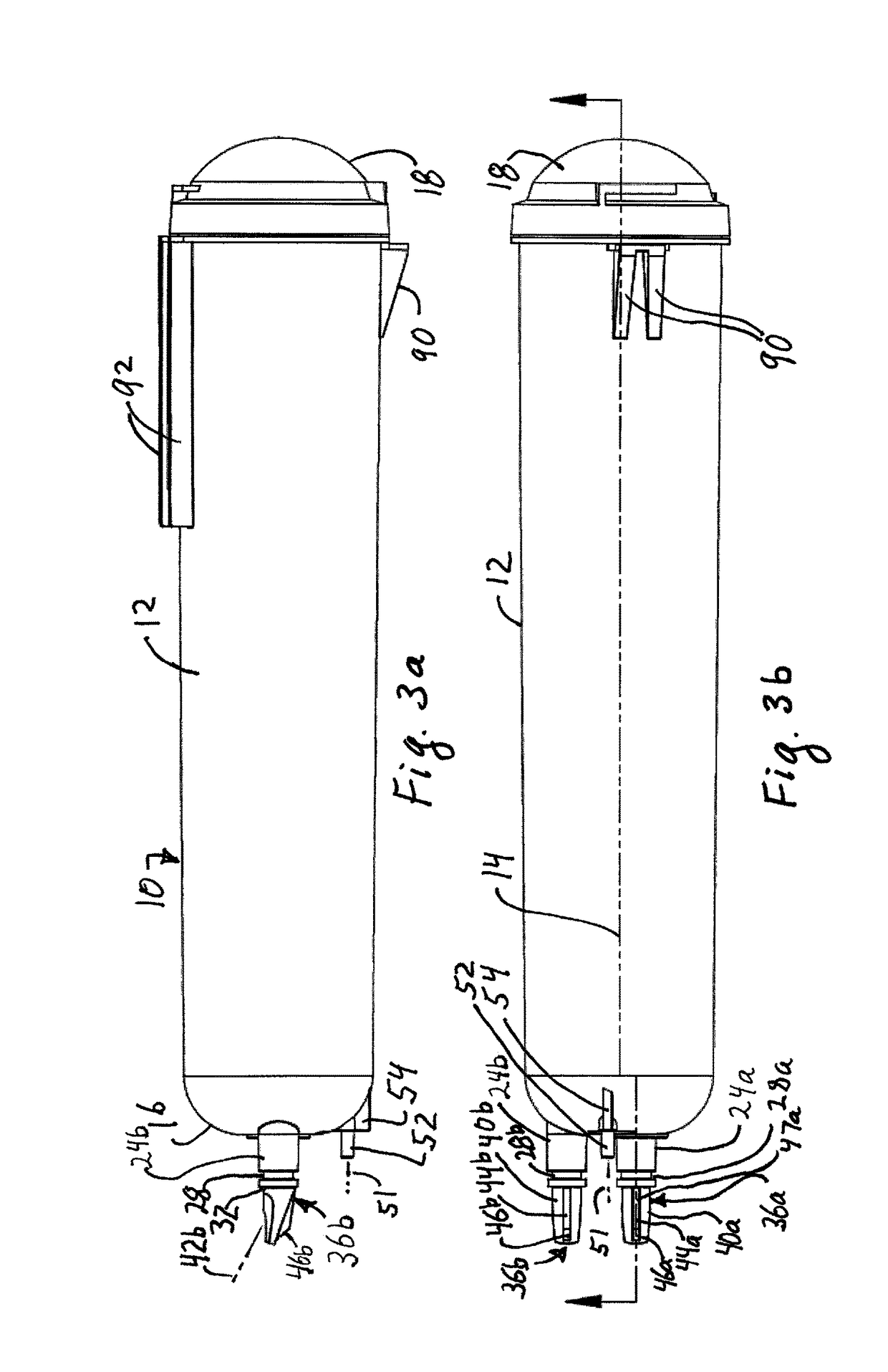
[0044]Referring to FIGS. 1-9, a water filter cartridge 10 has a cartridge sidewall 12 that is typically cylindrical and extends along a longitudinal 14 passing through the centerline of the cylinder. The sidewall is closed by first and second ends 16, 18 so the sidewall and ends enclose a filter element 20. Internal passages 22 within the filter cartridge 10 direct unfiltered water through the filter element 20 and filtered water out of the filter element 20 through inlet and outlet nozzles that may take various shapes. In the depicted embodiment the inlet and outlet are separated rather than being coaxial.

[0045]First and second tubes 24 extend from the first end 16 of cartridge 10. Thus, first tube 24a and second tube 24b respectively extend from the first end 16 of the cartridge 10. The tubes 24 each have an inner passage 26, so first tube 24 has inner passages 26a and second tube 24b has second inner passage 26b, each passage extending along a length of the respective tube 24a, 2...


PUM

PropertyMeasurementUnit
angleaaaaaaaaaa
angleaaaaaaaaaa
distanceaaaaaaaaaa

Abstract

A water filter cartridge has an end cap with separate inlet and outlet nozzles connected to the end of a cylindrical tube that extends from the end cap. The nozzles are slanted and laterally offset from the cylindrical tube. A cam surface on the outer side of the nozzles actuates valves in a mating manifold. The passage in the nozzles is conical, expanding toward the nozzle end and opening onto a portion of the nozzle side to form a sharper tip. Expanding ice pushes itself out of the conical passage and facilitates ice removal. The narrow end of the conical passage facilitates breakage and removal of ice from the nozzle.

Description

CROSS-REFERENCE TO RELATED APPLICATIONS[0001]The application claims the benefit under 35 U.S.C. §119(e) to Provisional Patent Application No. 62 / 001,472 filed May 21, 2014 the entire contents of which are incorporated herein by reference.BACKGROUND[0002]The present invention relates generally to water filter cartridges used in home and business water filter systems, and optionally used in commercial applications. Current filter systems have a manifold with a manifold inlet port connected to a source of water and a manifold outlet port connected to a dispenser for the filtered water, such as a household refrigerator, or an apparatus using filtered water such as a coffee maker. The manifold typically has a cylindrical, cup shaped interior with one or more receptacles for an inlet and outlet nozzle, and occasionally a recess for a bypass valve actuator. If the inlet and outlet nozzles are coaxial then there is usually one receptacle for the inlet and outlet flow of unfiltered and filte...

Claims


Application Information

Patent Timeline
Patent Type & Authority Patents(United States)
IPC IPC(8): B01D27/08B01D35/147B01D29/17C02F1/00B01D29/15B01D35/30B01D35/14B01D35/153
CPCB01D35/14C02F1/001B01D29/15B01D35/147B01D35/153B01D35/30B01D27/08F25D2323/121B01D2201/29B01D2201/291C02F2201/006B01D2201/303B01D2201/4007B01D2201/4053
Inventor BAIRD, MICHAEL T.
Owner TST WATER INC
Why Eureka
Try Eureka