De-icing arrangement and method for de-icing a structural element

a structural element and arrangement technology, applied in the direction of de-icing equipment, aircraft components, transportation and packaging, etc., can solve the problems of ice accretion on aircrafts, serious perturbations of flying conditions, and threatening events, and achieve the effect of improving the de-icing of structural elements

Inactive Publication Date: 2018-01-30
SAAB AB
View PDF14 Cites 0 Cited by
  • Summary
  • Abstract
  • Description
  • Claims
  • Application Information

AI Technical Summary

Benefits of technology

[0009]One objective of the present invention is to provide an improved de-icing of a structural element, such as a wing of an aircraft or a blade of a wind power installation.
[0016]With the arrangement above the distribution between generation of mechanical force and heat can be controlled. Further, with the arrangement above, the power required for each electromagnetic pulse though the structural element can be reduced. Thereby, the use of available power can be optimized to increase the performance of the de-icing.
[0017]Further, performance of a platform exposed to harsh weather conditions giving rise to ice accretion, can be improved. For example, problems with melted ice flowing over the structural element, which melted ice risks freezing in ice accretion formations on the structural element, can be reduced as heating can be minimized with the selection of the capacitor(s) discharged for providing the excitation pulse.

Problems solved by technology

Aircrafts are continuously exposed to varying climatic conditions and in this regard, ice accretion is a threatening event.
Ice accretion is known to cause serious perturbations to the flying conditions due to ice formations on aerodynamic surfaces of aircraft.
Ice accretion on aircrafts is a very complex physical process.
The selection of an adequate ice rejection technique is thus a difficult task.
One of the issues is the growing need for fuel consumption reductions.
Especially when using electromechanical de-icing systems (EMEDS) also the power output for driving the de-icing system is an issue and it is desirable to minimize the peak power output for the electro-mechanical de-icing system.

Method used


Image

  • De-icing arrangement and method for de-icing a structural element
  • De-icing arrangement and method for de-icing a structural element
  • De-icing arrangement and method for de-icing a structural element

Examples


Embodiment Construction

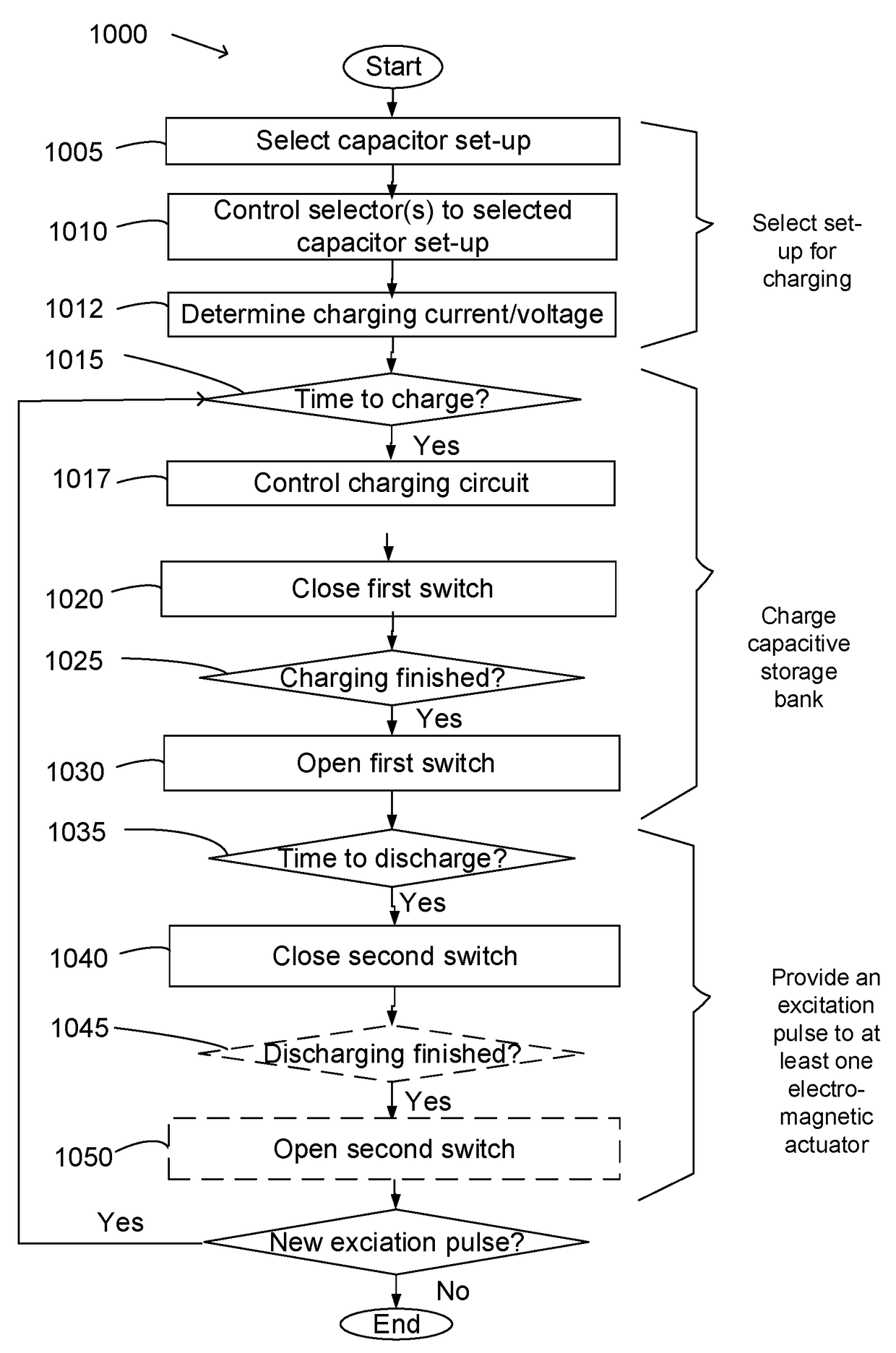
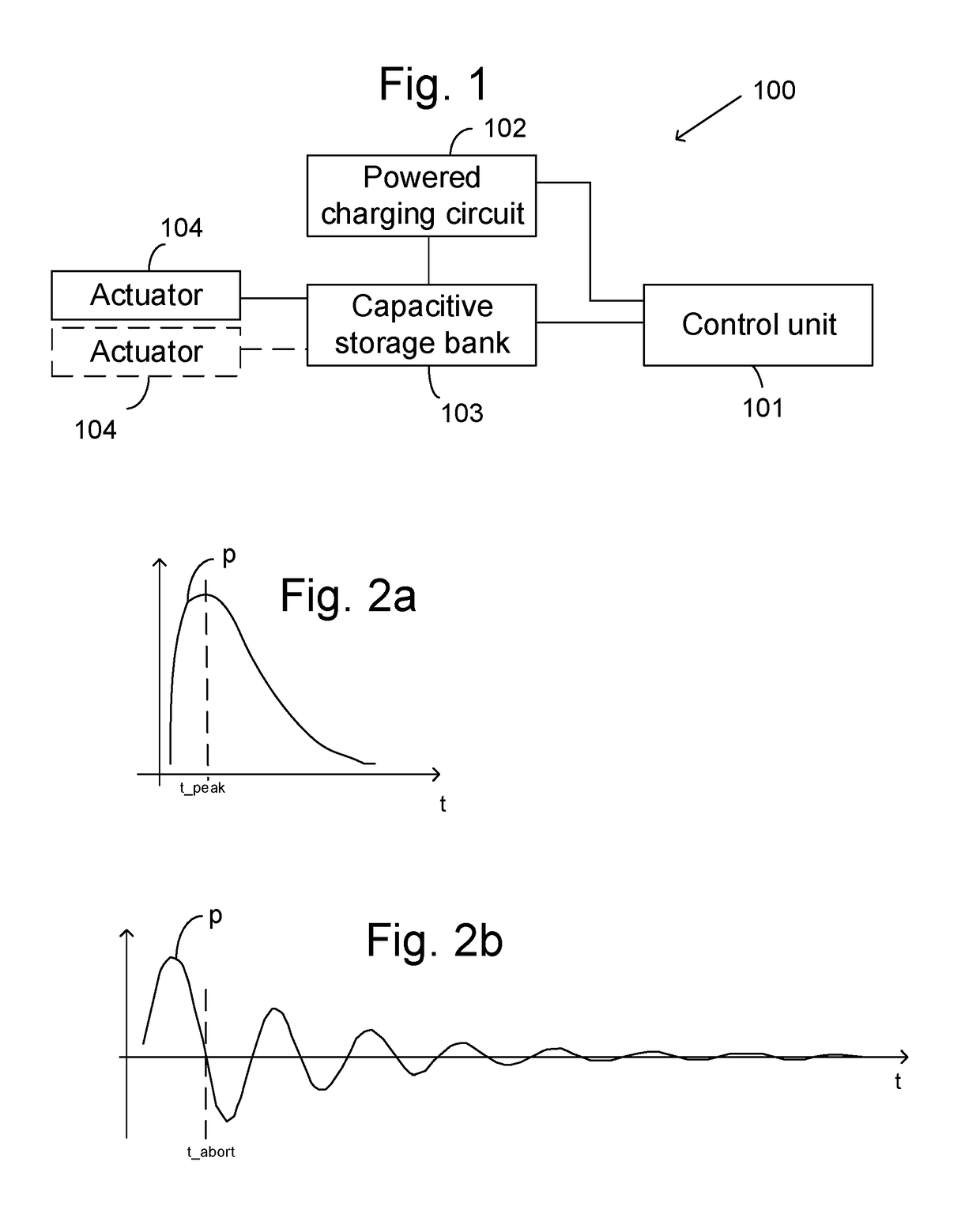
[0043]A de-icing arrangement for de-icing a structural element comprises at least one actuator for removing ice from the structural element, a capacitive storage bank and a control unit arranged to control discharge of the capacitive storage bank to provide an excitation pulse to the at least one electromagnetic actuator so as to force the actuator to apply a mechanical force on the structural element so as to provide a chock in the structural element. This may result in removal of ice from the structural element. The actuator is arranged to expand in at least one direction when fed with the excitation pulse. The actuator is arranged in relation to the structural element so that mechanical force caused by the expansion on the structural element will be applied to the structure element.

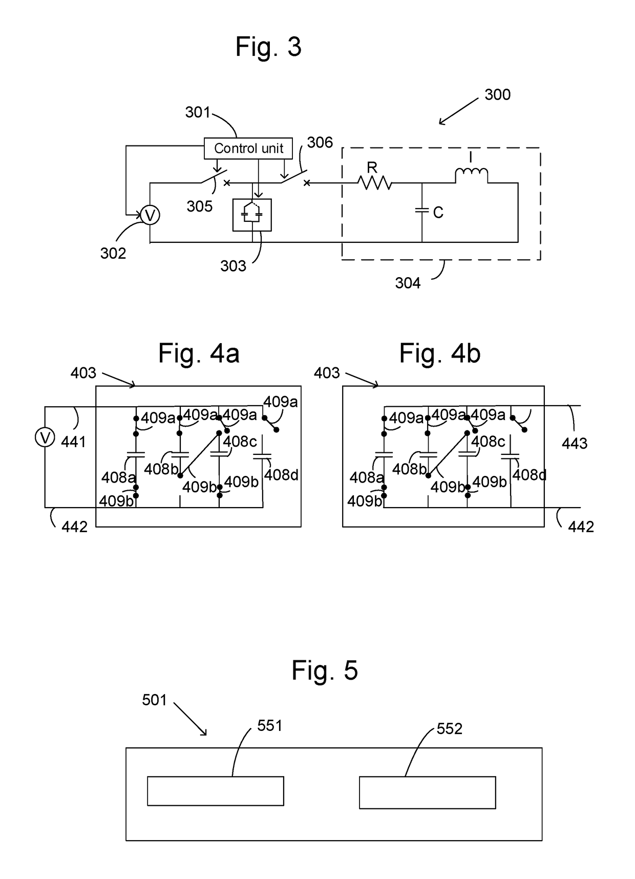
[0044]The capacitive storage bank comprises a plurality of selectable capacitors of different capacitance. The control unit is arranged to select at least one capacitor for charging having a total capa...


PUM


Abstract

A de-icing arrangement and method for de-icing a structural element. The arrangement includes at least one electromagnetic actuator, a capacitive storage bank, a control unit arranged to provide an excitation pulse to the at least one electromagnetic actuator, and a charging circuit arranged to charge the capacitive storage bank. The at least one electromagnetic actuator is arranged to expand in at least one direction when fed with the excitation pulse. The at least one electromagnetic actuator is placed in relation to the structural element so as to apply a mechanical force caused by the expansion on the structural element. The capacitive storage bank includes a plurality of selectable capacitors of different size. The control unit is arranged to select at least one capacitor for charging having a size such that current discharge of the capacitive storage bank into the at least one electromagnetic actuator generates a desired distribution between heat and mechanical power.

Description

CROSS-REFERENCE TO RELATED APPLICATIONS[0001]The application is the national phase under 35 U.S.C. §371 of PCT / SE2012 / 051351 filed 6 Dec. 2012.TECHNICAL FIELD[0002]The present invention relates to a de-icing arrangement and method for de-icing a structural element by means of at least one electromagnetic actuator.BACKGROUND ART[0003]Aircrafts are continuously exposed to varying climatic conditions and in this regard, ice accretion is a threatening event. Ice accretion is known to cause serious perturbations to the flying conditions due to ice formations on aerodynamic surfaces of aircraft.[0004]Ice accretion on aircrafts is a very complex physical process. The selection of an adequate ice rejection technique is thus a difficult task. The technique to be selected must be made compatible with a number of constraints comprising material properties, fatigue, dynamic deformation while in flight, repairing and servicing constraints, durability etc, just to name a few.[0005]One of the issu...

Claims


Application Information

Patent Timeline
Patent Type & Authority Patents(United States)
IPC IPC(8): B64D15/12B64D15/16
CPCB64D15/12B64D15/163
Inventor HADEN, BERTILBACKSTROM, MATS
Owner SAAB AB
Why Eureka
Try Eureka