Polarizing touch screen panel and display apparatus comprising the same

a touch screen panel and display device technology, applied in the direction of polarizing elements, instruments, computing, etc., can solve the problems of heavy optical loss, limited size of grid polarizer manufactured at a time, and considerable loss of light source emission, so as to improve touch sensitivity, improve image quality, and effect of forming a conductive structur

Inactive Publication Date: 2017-08-22
SAMSUNG ELECTRONICS CO LTD
View PDF13 Cites 0 Cited by
  • Summary
  • Abstract
  • Description
  • Claims
  • Application Information

AI Technical Summary

Benefits of technology

[0011]According to an example embodiment, a large-sized wire grid polarizer formed by a plurality of wire grid polarizers may be used to realize the touch-screen panel, thereby reducing costs and simplifying the structure while manufacturing a large-sized display apparatus with a touch screen function. For example, the conductive area for the touch sensing signal and the nonconductive area are provided in the seam area between the plurality of wire grid polarizers, thereby overcoming a problem of electrification or non-electrification due to the seam area between the plurality of touch sensing signals.
[0035]In the connection area, the number of grids, which are not connected to the electrodes, may be determined to prevent and / or reduce interference of the touch sensing signal between adjacent grids of the grid sub-group. Thus, it is possible to determine an optimum number of grids for transmitting a touch sensing signal within the grid sub-group.

Problems solved by technology

The light emitted from the light source is considerably lost while passing through optical elements of the backlight unit, and a polarizer of the display panel also absorbs quite a bit of the light traveling toward the panel, thereby resulting in a heavy optical loss.
However, the wire grid polarizer manufactured at a time is limited to a certain size, and it is therefore difficult to form a large-sized wire grid polarizer.
If a touch screen panel for sensing a user's touch input is provided separately from the polarizer in the display panel, problems arise in that manufacturing costs increase, a structure becomes complicated, and the touch screen panel, which is expensive, has to be replaced when it has a defect.

Method used


Image

  • Polarizing touch screen panel and display apparatus comprising the same
  • Polarizing touch screen panel and display apparatus comprising the same
  • Polarizing touch screen panel and display apparatus comprising the same

Examples


Embodiment Construction

[0056]Example embodiments will be described in greater detail with reference to accompanying drawings so as to be readily understood by a person having an ordinary skill in the art. The disclosure may be achieved in various forms and should not be construed as being limited to the following example embodiments. For clarity, parts not directly related to the disclosure may be omitted, and like reference numerals refer to like elements throughout.

[0057]Features of elements included in a display panel according to an example embodiment will be first described in greater detail with reference to FIG. 1, and FIGS. 2 to 16 may also be referred to, as necessary.

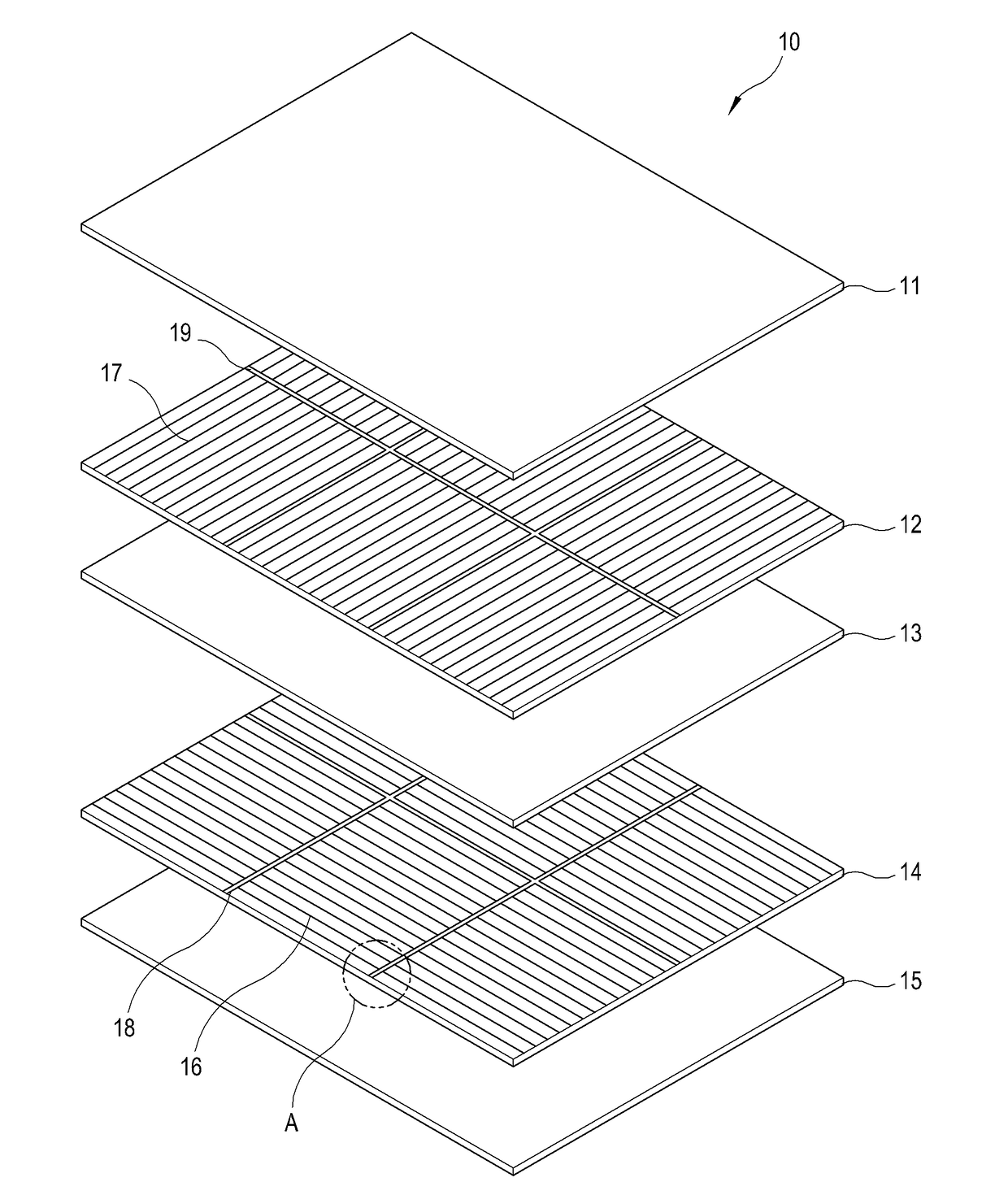
[0058]FIG. 1 is an exploded perspective view illustrating an example display panel. As illustrated in FIG. 1, a display panel 10 may include, for example, a first glass substrate 11 and a second glass substrate 15, which are arranged facing each other; a liquid crystal layer 13 interposed in between the first glass substrate 11 and ...


PUM

PropertyMeasurementUnit
sizeaaaaaaaaaa
heightaaaaaaaaaa
heightaaaaaaaaaa

Abstract

Disclosed is a display panel including: a liquid crystal layer; and a polarization-touch sensing layer stacked on one side of the liquid crystal layer, the polarization-touch sensing layer comprising: a plurality of wire grid areas configured to polarize incident light from a light source the wire grid areas including grid patterns configured to transmit a plurality of touch sensing signals; and a plurality of seam areas arranged in between the plurality of wire grid areas and including a conductive area configured to transmit the touch sensing signal between a pair of adjacent grid patterns, and a nonconductive area configured to block the plurality of touch sensing signals from being transmitted between the pair of grid patterns.

Description

CROSS-REFERENCE TO RELATED APPLICATION[0001]This application is based on and claims priority under 35 U.S.C. §119 to Korean Patent Application No. 10-2015-0021136, filed on Feb. 11, 2015 in the Korean Intellectual Property Office, the disclosure of which is incorporated by reference herein in its entirety.BACKGROUND[0002]Field[0003]Apparatuses and methods of the disclosure relate generally to a display panel and a display apparatus, and for example, to a display panel and a display apparatus, in which a wire grid polarizer is used for a touch screen.[0004]Description of Related Art[0005]A liquid crystal display panel transmits light emitted from a light source such as a backlight unit so that a user can view an image. The light emitted from the light source is considerably lost while passing through optical elements of the backlight unit, and a polarizer of the display panel also absorbs quite a bit of the light traveling toward the panel, thereby resulting in a heavy optical loss. ...

Claims


Application Information

Patent Timeline
Patent Type & Authority Patents(United States)
IPC IPC(8): G06F3/041G02B5/30G02F1/1333G06F3/044G02F1/1335
CPCG02B5/3058G02F1/13338G06F3/044G02F1/133512G02F2001/133548G06F2203/04103G06F2203/04112G06F3/0445G02F1/133548G02F1/133528G06F3/041
Inventor LEE, JOO WONKANG, YOUNG MOSUNG, JUN HOLEE, DONG JUNJUNG, IL YONG
Owner SAMSUNG ELECTRONICS CO LTD
Why Eureka
Try Eureka