Metal terminals

a technology of metal terminals and terminals, which is applied in the direction of coupling contact members, coupling device connections, electrical devices, etc., can solve the problems of shrinking space available for arranging the connecting device, and still required space for female terminals and male terminals, so as to reduce the required mounting space, the effect of connecting operation and shortening the tim

Active Publication Date: 2017-08-22
MOLEX INC
View PDF14 Cites 0 Cited by
  • Summary
  • Abstract
  • Description
  • Claims
  • Application Information

AI Technical Summary

Benefits of technology

[0008]In order to solve the aforementioned problems, the object of the Present Disclosure is to provide metal terminals in which a pair of metal terminals having inverted profiles relative to each other but able to be mated with each other can be mounted directly onto conductive components, so that the connecting operation can be performed easily in a short period of time, the required mounting space can be reduced, the structure can be simplified and costs can be reduced, and the number of applications can be increased. In order to achieve this purpose, the Present Disclosure is metal terminals having a first terminal made of a conductive metal, and a second terminal made of a conductive metal and mated with the first terminal; the first terminal having a first main body portion, a first fixed portion fixed to a connecting portion of a first conductive component, a first contact portion, and a first lock portion; the second terminal having a second main body portion, a second fixed portion fixed to a connecting portion of a second conductive component, a second contact portion contacting the first contact portion, and a second lock portion; the first lock portion including a first engaging portion arranged on a surface of the first main body portion; and the second lock portion including a pair of second engaging portions arranged on opposing surfaces of the second main body portion.
[0011]The Present Disclosure is able to provide metal terminals in which a pair of metal terminals having inverted profiles relative to each other but able to be mated with each other can be mounted directly onto conductive components, so that the connecting operation can be performed easily in a short period of time, the required mounting space can be reduced, the structure can be simplified and costs can be reduced, and the number of applications can be increased.

Problems solved by technology

As electrical devices and electronic devices become smaller, the space available to arrange the connecting device shrinks.
However, a space larger than the female terminals and male terminals themselves is still required when female connectors and male connectors are used.

Method used


Image

  • Metal terminals
  • Metal terminals
  • Metal terminals

Examples


Embodiment Construction

[0025]While the Present Disclosure may be susceptible to embodiment in different forms, there is shown in the Figures, and will be described herein in detail, specific embodiments, with the understanding that the Present Disclosure is to be considered an exemplification of the principles of the Present Disclosure, and is not intended to limit the Present Disclosure to that as illustrated.

[0026]As such, references to a feature or aspect are intended to describe a feature or aspect of an example of the Present Disclosure, not to imply that every embodiment thereof must have the described feature or aspect. Furthermore, it should be noted that the description illustrates a number of features. While certain features have been combined together to illustrate potential system designs, those features may also be used in other combinations not expressly disclosed. Thus, the depicted combinations are not intended to be limiting, unless otherwise noted.

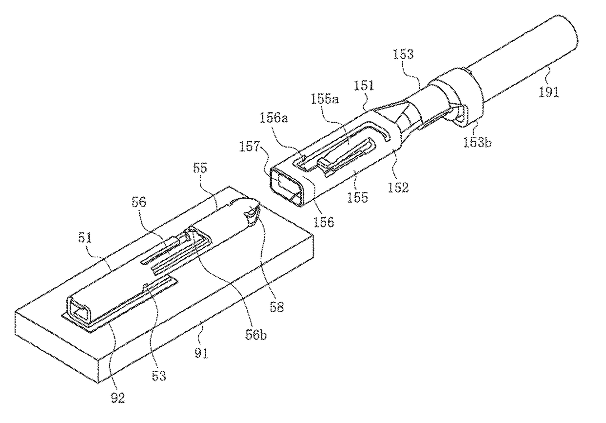
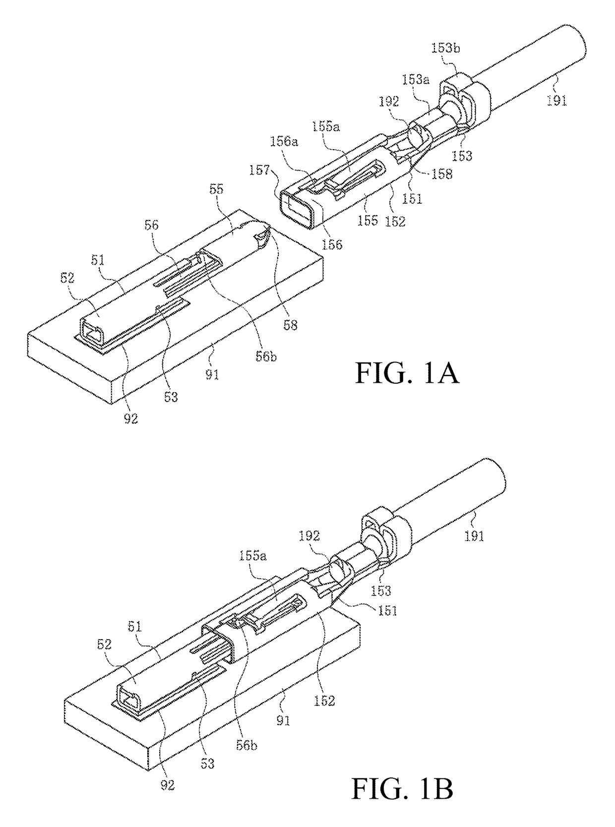
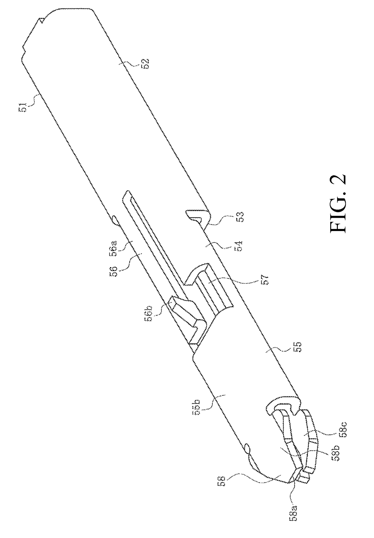
[0027]In the embodiments illustrated in ...


PUM


Abstract

The metal terminals are a first terminal, and a second terminal mated with the first terminal, the first terminal has a first main body portion, a first contact portion, and a first lock portion, the second terminal has a second main body portion, a second contact portion contacting the first contact portion, and a second lock portion locking the first lock portion. The first lock portion includes a first engaging portion arranged on a surface of the first main body portion, and the second lock portion including a pair of second engaging portions arranged on opposing surfaces of the second main body portions.

Description

REFERENCE TO RELATED APPLICATIONS[0001]The Present Disclosure claims priority to prior-filed Japanese Patent Application No. 2014-018312, entitled “Metal Terminals,” filed on 3 Feb. 2014 with the Japanese Patent Office. The content of the aforementioned patent application is incorporated in its entirety herein.BACKGROUND OF THE PRESENT DISCLOSURE[0002]The Present Disclosure relates, generally, to metal terminals, and, more particularly[0003]Various conventional connecting devices that are currently used have male and female connectors for connecting an electrical wire such as a cable to an electrical device or an electronic device. A technique has been proposed for inverting the orientations of male connectors and female connectors able to engage each other when the arrangement of terminals changes. An example is disclosed in Japanese Patent Application No. 57-084580, the content of which is incorporated in its entirety herein.[0004]FIGS. 12A and 12B are diagrams showing a conventio...

Claims


Application Information

Patent Timeline
Patent Type & Authority Patents(United States)
IPC IPC(8): H01R13/20H01R12/73H01R12/75H01R12/70
CPCH01R13/20H01R12/707H01R12/732H01R12/75
Inventor EBISAWA, SATOSHINIITSU, TOSHIHIROINUKAI, HITOMI
Owner MOLEX INC
Why Eureka
Try Eureka