Balance filter

a filter and balance technology, applied in the field of balance filters, can solve the problems of large mounting space required inside the communication apparatus, increase in total insertion loss, and loss of insertion, so as to reduce or prevent interference with each other, increase the strength of electromagnetic coupling, and reduce or prevent interference.

Active Publication Date: 2020-03-24
MURATA MFG CO LTD
View PDF25 Cites 1 Cited by
  • Summary
  • Abstract
  • Description
  • Claims
  • Application Information

AI Technical Summary

Benefits of technology

[0014]In this case, it is preferable that a third capacitor is connected in parallel with the first inductor of the low pass filter. In this case, a trap may be provided on a higher frequency side outside a pass band of the low pass filter, and the function of the low pass filter is thus improved.
[0026]Furthermore, balance filters according to preferred embodiments of the present invention achieve, with one balance filter, a function conventionally achieved by using a divider and two balance filters. The number of components is reduced, and miniaturization is able to be achieved. Therefore, for communication apparatuses in which balance filters according to preferred embodiments of the present invention are mounted, a required mounting space is able to be reduced.

Problems solved by technology

First, a signal line connected to the antenna Ant is divided by the divider 300, and therefore, there is a problem in which insertion loss occurs in a signal.
Furthermore, insertion loss also occurs in each of the balance filters 200, and therefore, there is a problem in which the total insertion loss increases.
Therefore, a large mounting space is required inside the communication apparatus, and there is a problem in which the size of a communication apparatus increases.
Moreover, there is a problem in which manufacturing is complicated due to a large number of components.

Method used


Image

  • Balance filter
  • Balance filter
  • Balance filter

Examples


Embodiment Construction

[0035]Hereinafter, preferred embodiments of the present invention will be described with reference to drawings.

[0036]Individual preferred embodiments illustratively represent preferred embodiments of the present invention, and therefore, the present invention is not limited to the contents of the preferred embodiments. Furthermore, contents described in different preferred embodiments may be combined and implemented, and contents of such implementation are also included in the present invention. Drawings are intended to aid understanding of the preferred embodiments and are not necessarily rendered strictly. For example, rendered components or the ratio of dimensions of the components may not be the same or substantially the same as the ratio of dimensions of those described herein. Furthermore, components described herein may be omitted in the drawings or the number of components described herein may be reduced in the drawings.

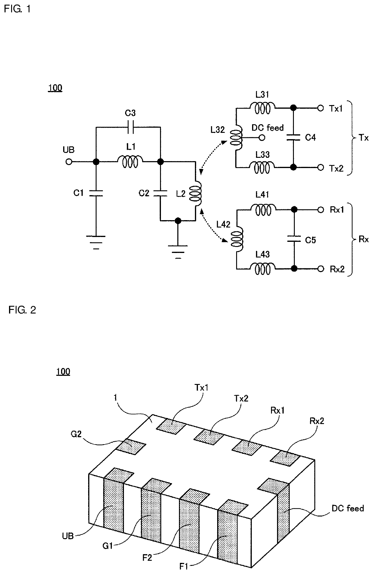
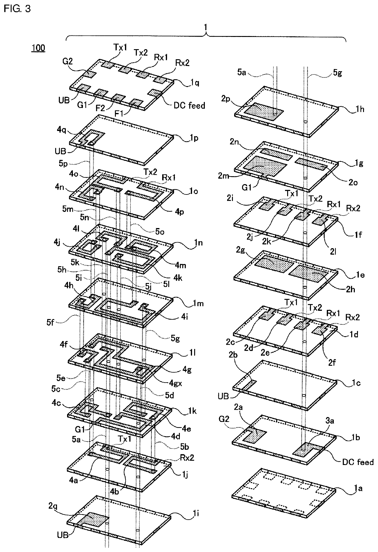
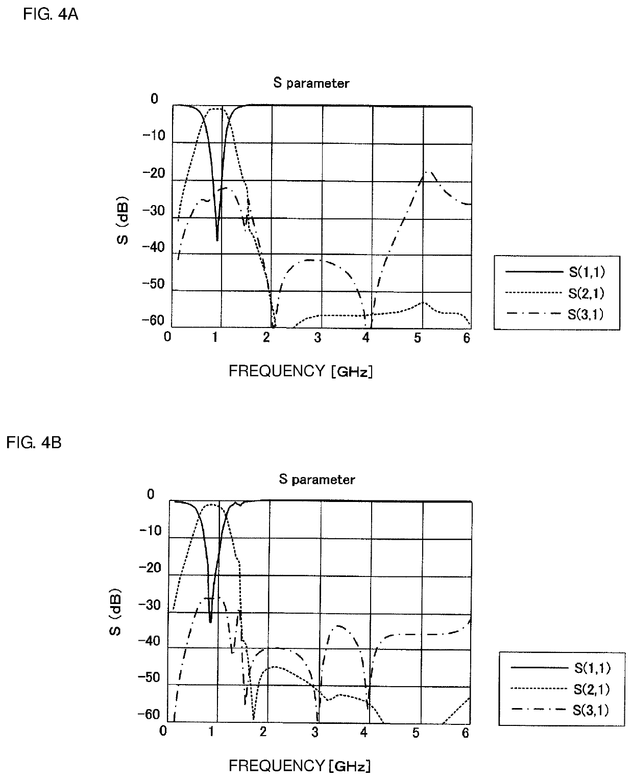
[0037]FIGS. 1 to 3 illustrate a balance filter 100 acco...


PUM

PropertyMeasurementUnit
impedanceaaaaaaaaaa
frequencyaaaaaaaaaa
capacitanceaaaaaaaaaa

Abstract

A small-sized balance filter includes an unbalanced terminal and two pairs of balanced terminals and has a low signal insertion loss. An unbalanced terminal, a first balanced terminal including first and second terminals, and a second balanced terminal Rx including first and second terminals are provided. An unbalanced-side inductor is provided between the unbalanced terminal and the ground, first balanced-side inductors are provided between the first and second terminals of the first balanced terminal, second balanced-side inductors are provided between the first and second terminals of the second balanced terminal, and the unbalanced-side inductor is electromagnetic-field-coupled to each of the first and second balanced-side inductors.

Description

CROSS REFERENCE TO RELATED APPLICATIONS[0001]This application claims the benefit of priority to Japanese Patent Application No. 2015-207576 filed on Oct. 21, 2015 and is a Continuation Application of PCT Application No. PCT / JP2016 / 077605 filed on Sep. 19, 2016. The entire contents of each application are hereby incorporated herein by reference.BACKGROUND OF THE INVENTION1. Field of the Invention[0002]The present invention relates to a balance filter, and more particularly, to a small-sized balance filter including an unbalanced terminal and two pairs of balanced terminals and having a low signal insertion loss.2. Description of the Related Art[0003]To reduce external impact of noise, an RF (Radio Frequency) circuit of a communication apparatus and a peripheral circuit thereof may use a balanced line as a signal line. For example, input of an Rx signal from an antenna to an RF circuit and output of a Tx signal from the RF circuit to the antenna may be performed using a balanced line....

Claims


Application Information

Patent Timeline
Patent Type & Authority Patents(United States)
IPC IPC(8): H03H7/42H04B1/58H03H7/01H03H7/48H03H7/46H01F27/00H03H7/09H01F17/00H01P5/10H03H7/38H03H1/00
CPCH03H7/0123H04B1/581H01F27/00H03H7/482H01F17/00H03H7/09H03H7/422H03H7/0115H03H7/461H03H7/38H03H2001/0085
Inventor TANIGUCHI, TETSUO
Owner MURATA MFG CO LTD
Why Eureka
Try Eureka