Device for adjusting camber and/or toe of a vehicle wheel

a technology for camber and/or toe, which is applied in the direction of vehicle springs, resilient suspensions, vehicle components, etc., can solve the problems of inadvertent influence on the camber and/or toe behavior of the wheel carrier, and achieve the effect of reducing the required mounting spa

Inactive Publication Date: 2019-05-14
AUDI AG
View PDF38 Cites 1 Cited by
  • Summary
  • Abstract
  • Description
  • Claims
  • Application Information

AI Technical Summary

Benefits of technology

[0010]According to the characterizing portion of the independent patent claim the torque bridge between the wheel-side carrier part and the axle-side guide part is configured as a torque transmission element, which upon support of the carrier part that is impinged with the brake torque on the guide part, generates a force component with which the wheel-side carrier part is impinged during the braking process. The torque transmission element thus converts the braking torque into the force component. By means of the force component an unintended steering of the wheel-side carrier part due to kinetic properties of the wheel carrier can be prevented during the braking process, which otherwise would lead to an unintended change of camber or toe of the vehicle wheel during the braking process.
[0011]The torque transmission element can be of arbitrary design. For reducing required mounting space it is advantageous when the torque transmission element is at least one coupling rod, which can absorb pulling and also compression forces. The coupling rod can be articulately connected respectively on a wheel-side instantaneous center of rotation at the wheel-side carrier part and on an axle-side instantaneous center of rotation on the axle-side guide part. Conventional torque bridges, for example a universal shaft or a metal bellow, are configured solely with a proper brake torque support in mind, i.e., torsion stiff with regard to the wheel axel but sufficiently resilient in order to not adversely affect the pivot movement of the wheel-side rotary part with carrier part coupled thereon. Such a torque bridge, however is not capable to act with the above-mentioned targeted force component on the wheel-side carrier part.

Problems solved by technology

In addition during the braking process forces and moments act on the vehicle wheel, which poses the risk of an inadvertent influence on the camber and / or toe behavior of the wheel carrier.

Method used


Image

  • Device for adjusting camber and/or toe of a vehicle wheel
  • Device for adjusting camber and/or toe of a vehicle wheel
  • Device for adjusting camber and/or toe of a vehicle wheel

Examples


Embodiment Construction

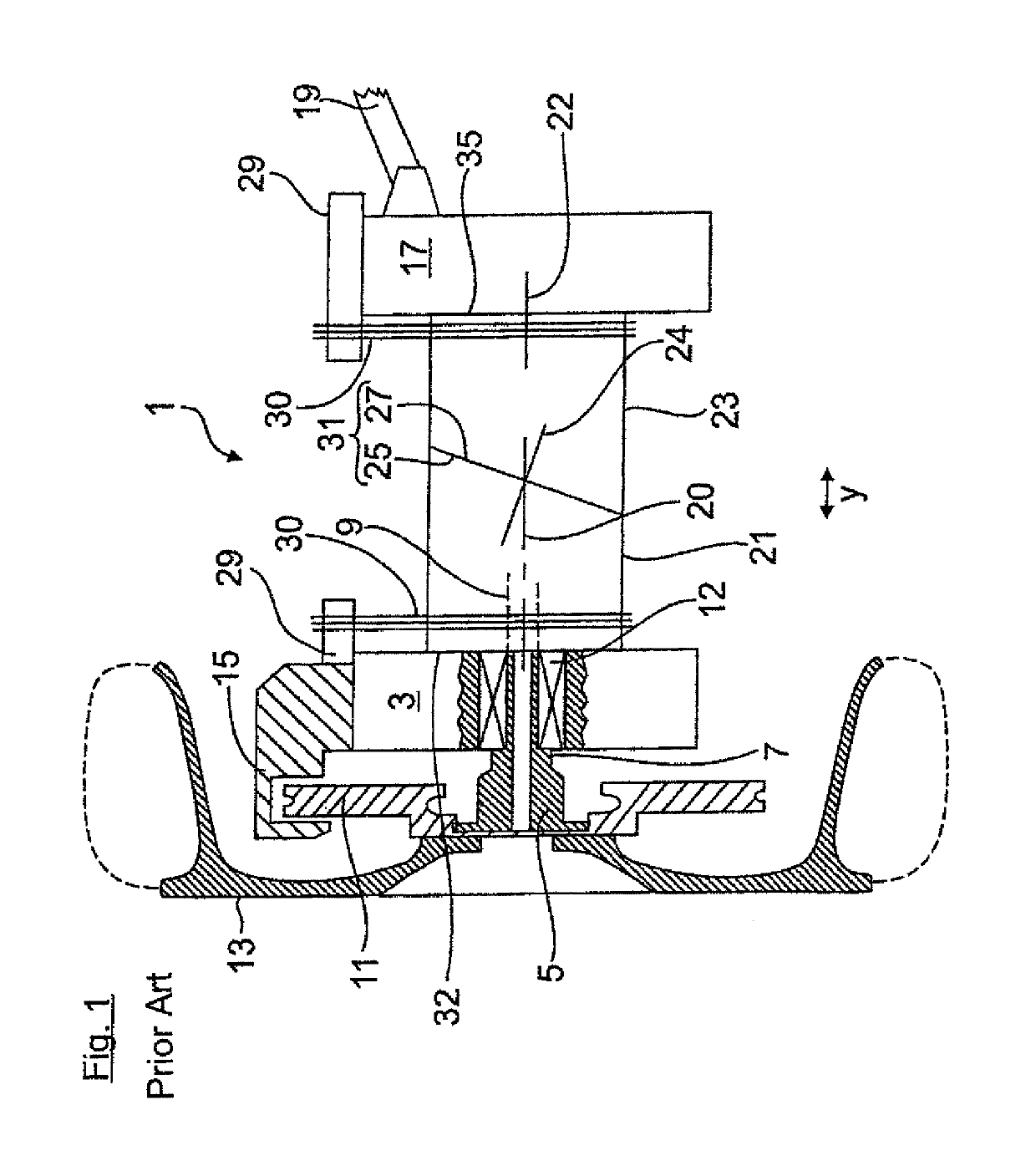
[0029]In order to facilitate understanding of the invention FIG. 1 shows a strongly schematic representation of a wheel carrier 1 of a vehicle wheel 13 known from the state of the art, which is not part of the invention.

[0030]The wheel carrier 1 has a carrier part 3 in which a wheel flange 5 is rotatably supported with its hub section 7 in a wheel bearing 12. On the wheel flange 5 a brake disc 11 and a vehicle wheel 13 is mounted with its wheel rim. The brake disc 11 together with a brake caliper 15 mounted on the carrier part 3 is a part of the brake system. Extending through the wheel carrier 1 is an articulated shaft which drives the vehicle wheel 13 and on whose constant velocity joint (only shown in FIGS. 2 to 4 with reference numeral 9) an also not shown central screw is screwed, with which the wheel bearing 12 is clamped via the wheel hub 5 and the constant velocity joint 9.

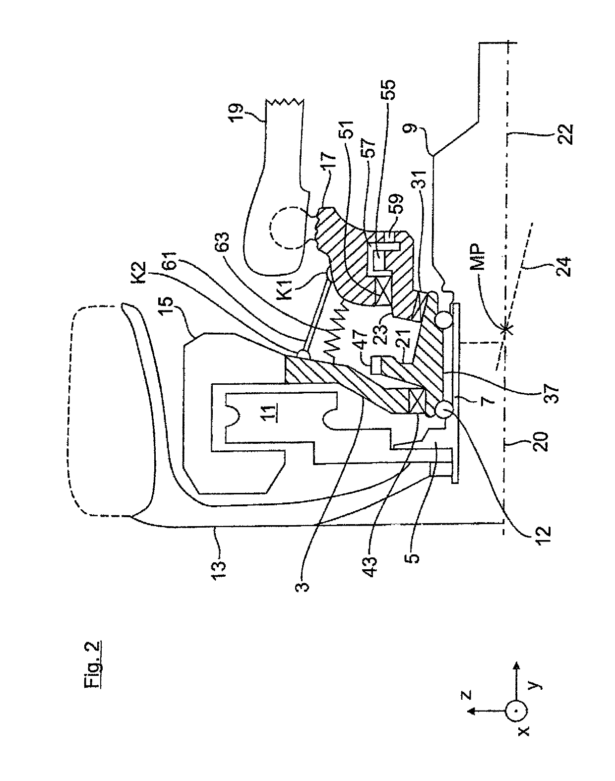
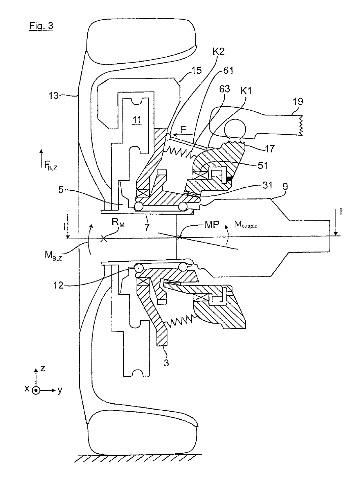
[0031]The wheel carrier 1 also has a guide part 17 on which in FIG. 1 exemplarily a control arm 19 of t...


PUM


Abstract

A device for adjusting camber and/or toe of a vehicle wheel of a motor vehicle, includes a wheel carrier including a wheel-side carrier part, an axle-side guide part and rotary parts arranged between the wheel-side carrier part and the axle-side guide part, the rotary parts being supported on a common bearing site for rotation relative to each other about a rotation axis, the wheel-side carrier part being rotatable about said rotation axis about an instantaneous center of rotation for toe or camber adjustment of the vehicle wheel and supporting a brake caliper interacting with a brake disc of the vehicle wheel; and a torque bridge configured as a torque transmission element which supports the wheel-side carrier part on the axle-side guide part when a braking moment acts on the wheel-side carrier part during a braking process, and which when supporting the wheel-side carrier part on the axle-side guide part generates a directed force component with which the wheel-side carrier part is impingable.

Description

CROSS-REFERENCES TO RELATED APPLICATIONS[0001]This application is the U.S. National Stage of International Application No. PCT / EP2015 / 001256, filed Jun. 22, 2015, which designated the United States and has been published as International Publication No. WO 2016 / 015801 and which claims the priority of German Patent Application, Serial No. 10 2014 011 110.5, filed Jul. 26, 2014, pursuant to 35 U.S.C. 119(a)-(d).BACKGROUND OF THE INVENTION[0002]The invention relates to a method for adjusting camber and / or toe of a motor vehicle wheel according to the preamble of patent claim 1.[0003]From DE 10 2009 058 489 A1 a generic device is known in which a wheel carrier for a vehicle wheel is configured multipart, i.e., with a wheel-side carrier part and an axle-side guide part and with rotary parts arranged there between. In the wheel-side carrier part a wheel bearing is integrated in which a wheel hub section of a wheel flange, which carries the vehicle wheel, can be articulately connected. The...

Claims


Application Information

Patent Timeline
Patent Type & Authority Patents(United States)
IPC IPC(8): B62D17/00B60G17/016B60G17/015
CPCB62D17/00B60G17/0152B60G17/0164B60G2200/46B60Y2400/405B60G2200/4622B60G2202/42B60G2206/50B60Y2300/02B60G2200/462
Inventor KLINGER, THOMASSCHMID, WOLFGANGBERINGER, HEINRICHGLAS, ACHIMVOLL, ULRICHBRAUMANDL, MICHAELPOURROY-SOLARI, VINCENT
Owner AUDI AG
Why Eureka
Try Eureka