

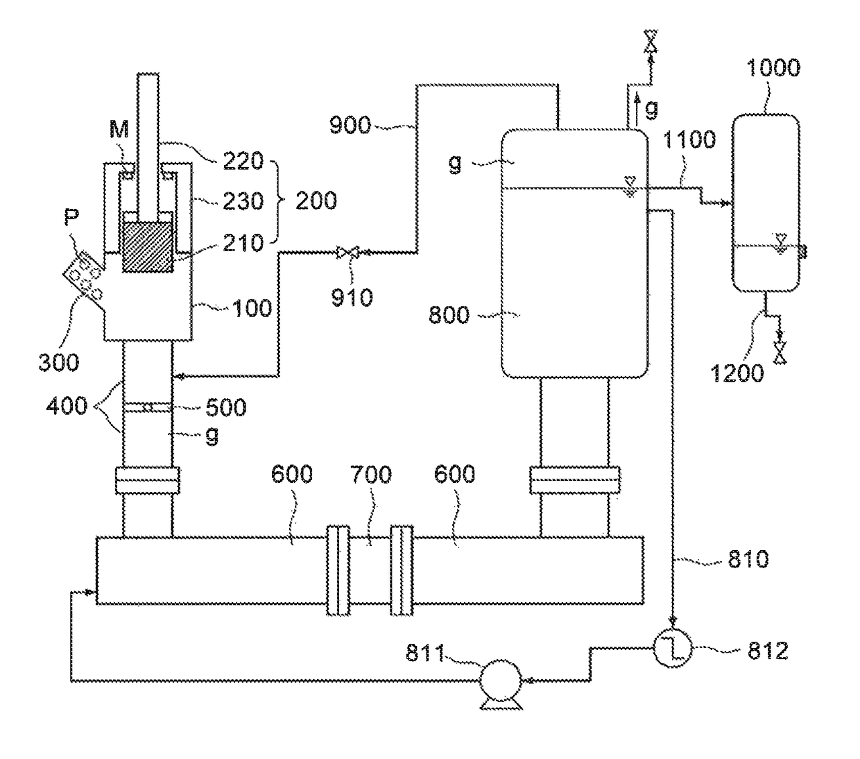
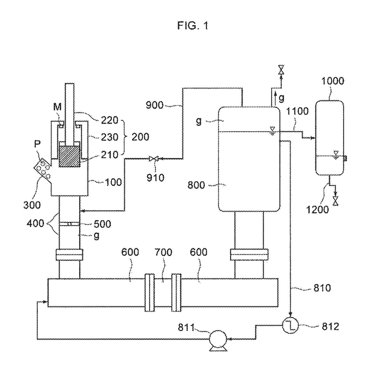
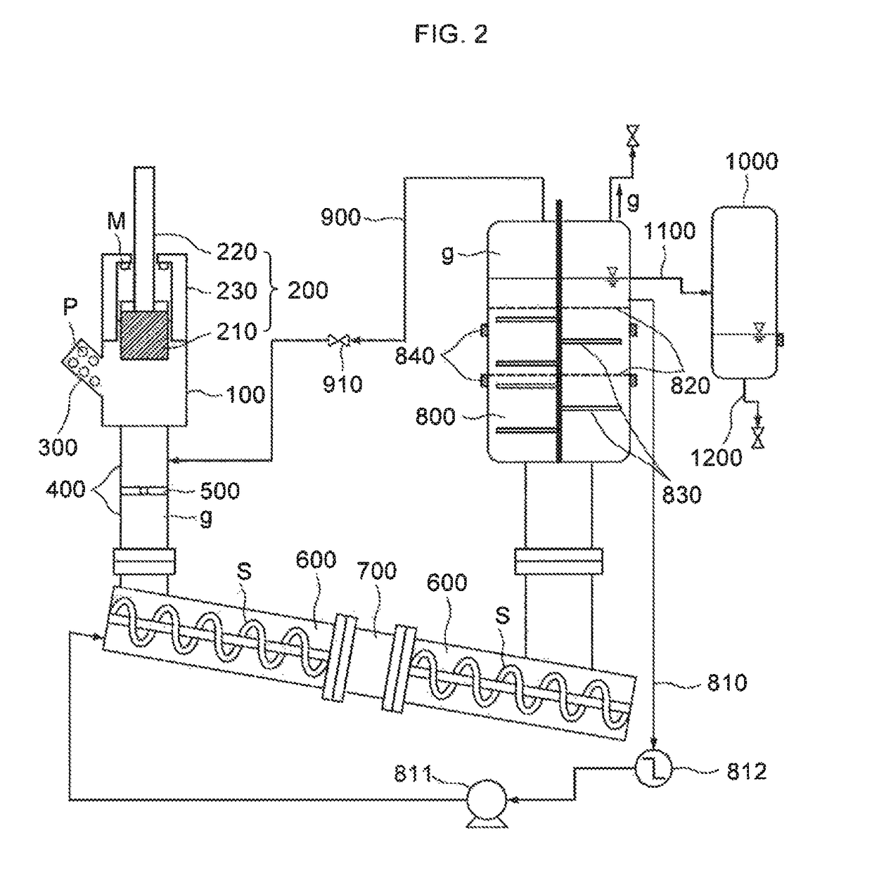
Apparatus for revaporizing gas hydrate pellets
a technology of gas hydrate pellets and apparatuses, which is applied in the direction of pressure vessels for chemical processes, energy-based chemical/physical/physico-chemical processes, organic chemistry, etc., can solve the problems of large amount of bog (boil off gas) generation, inability to produce a large amount of high-pressure gas continuously, and restricted economic feasibility of lng methods, etc., to achieve the effect of increasing the processed amount of gas hydrate pellet regasification
- Summary
- Abstract
- Description
- Claims
- Application Information
AI Technical Summary
Benefits of technology
Problems solved by technology
Method used
Image

Examples
Embodiment Construction
[0042]Since there can be a variety of permutations and embodiments of the present invention, a certain embodiment will be illustrated and described with reference to the accompanying drawings. This, however, is by no means to restrict the present invention to a certain embodiment, and shall be construed as including all permutations, equivalents and substitutes covered by the ideas and scope of the present invention. Throughout the description of the present invention, when describing a certain relevant conventional technology is determined to evade the point of the present invention, the pertinent detailed description will be omitted.
[0043]The terms used in the description are intended to describe certain embodiments only, and shall by no means restrict the present invention. Unless clearly used otherwise, expressions in a singular form include a meaning of a plural form. In the present description, an expression such as “comprising” or “including” is intended to designate a charac...
PUM
| Property | Measurement | Unit |
|---|---|---|
| pressure | aaaaa | aaaaa |
| pressure | aaaaa | aaaaa |
| temperature | aaaaa | aaaaa |
Abstract
Description
Claims
Application Information