Thermal energy harvesting device

a technology of thermal energy and energy harvesting device, which is applied in the direction of dynamo-electric components, dynamo-electric machines, electrical equipment, etc., can solve the problems of complex design and known thermal energy harvesting device utilizing sma

Active Publication Date: 2017-08-29
THE UNIVERSITY OF AKRON
View PDF12 Cites 0 Cited by
  • Summary
  • Abstract
  • Description
  • Claims
  • Application Information

AI Technical Summary

Problems solved by technology

However, known thermal energy harvesting devices utilizing an SMA suffer from various disadvantages, including having complex designs.

Method used


Image

  • Thermal energy harvesting device
  • Thermal energy harvesting device
  • Thermal energy harvesting device

Examples


Embodiment Construction

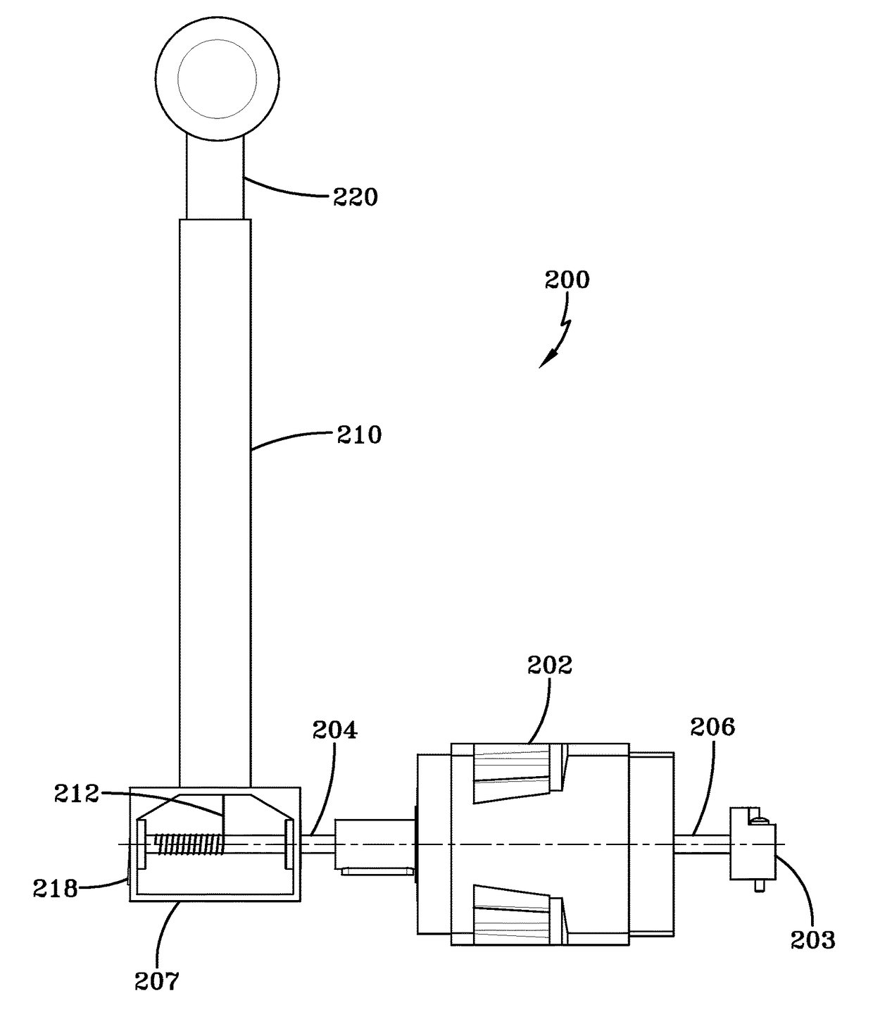
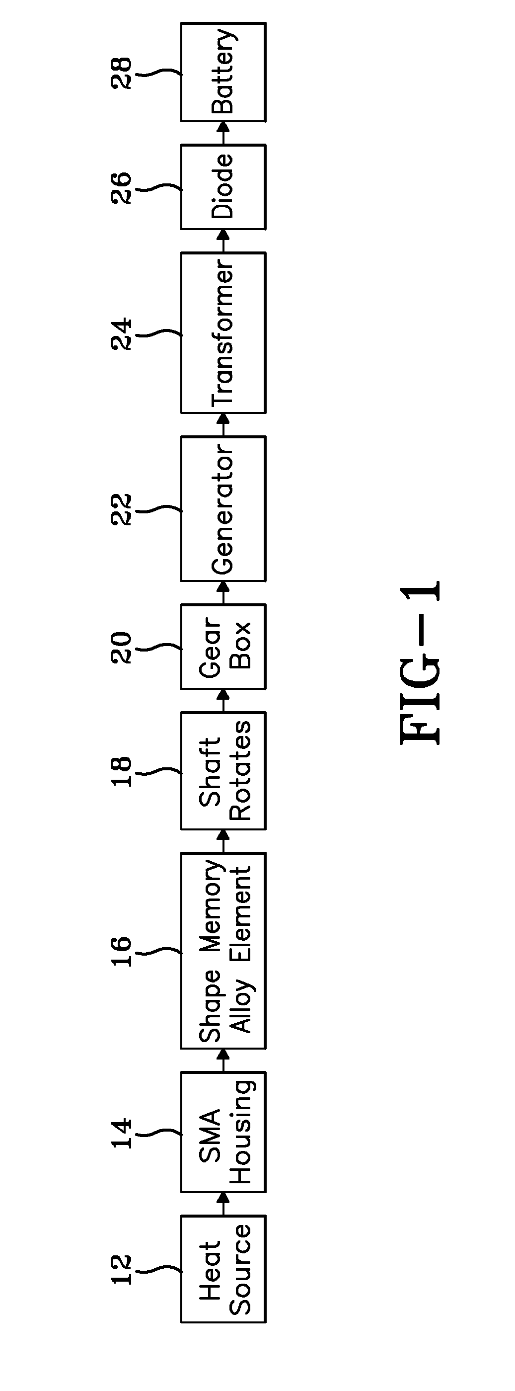
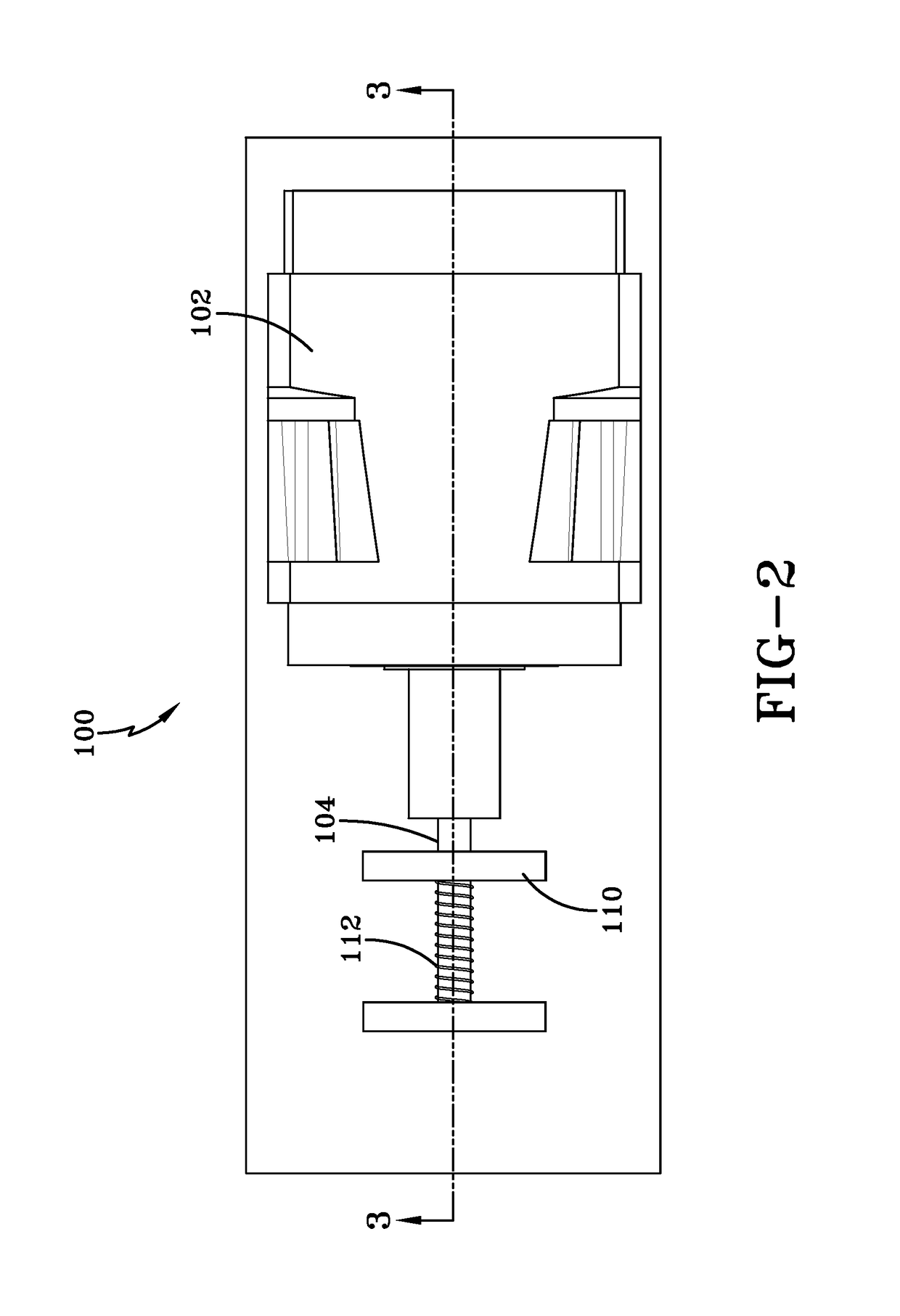
[0020]In one or more embodiments, a thermal energy harvesting device according to the concepts of the present disclosure includes a shape memory alloy (SMA) element. In one or more embodiments, the SMA element may be operatively coupled to a shaft operatively secured to a generator, where rotation of the shaft drives the generator to create electrical energy. In certain embodiments, the electrical energy created by the generator may be stored, such as in a rechargeable battery, for later use. In one or more embodiments, the SMA element and at least a portion of the shaft may be positioned within a chamber equipped with a temperature control mechanism to create increased temperature oscillation within the chamber. In certain embodiment, the SMA element may be provided in a helical configuration around a portion of the shaft.

[0021]The SMA element of the present disclosure refers to an element formed from a shape memory alloy (SMA). Shape memory alloys generally refer to a group of met...


PUM


Abstract

A thermal energy harvesting device includes a rotatable shaft and a shape memory alloy element secured to rotatable shaft. The shape memory alloy element is adapted to undergo a shape memory effect upon reaching a transition temperature, which causes rotation of the rotatable shaft. The rotatable shaft may be operatively connected to a generator or tachometer to convert the rotation of the shaft into electrical energy, which may then be stored in a rechargeable battery. In certain embodiments a gear box may be provided to increase the speed of rotation, and thereby increase the amount of electrical energy created.

Description

[0001]This application claims priority from U.S. Provisional Application Ser. No. 61 / 482,857 filed on May 5, 2011, which is incorporated herein by reference.FIELD OF THE INVENTION[0002]In one or more embodiments, the present disclosure is directed to an energy harvesting device that utilizes a shape memory alloy (SMA) to convert thermal energy into electrical energy. In certain embodiments, the SMA may generate rotation in a shaft that is operatively coupled to a generator.BACKGROUND OF THE INVENTION[0003]Thermal energy harvesting, also referred to as thermal energy scavenging, is the conversion of heat energy into electrical energy. The heat energy may be derived from any available sources, such as, for example, ambient heat in the atmosphere or waste heat generated by industrial chimneys, engines and the like. The electrical energy harvested from the thermal energy may then be used as a power source for a variety of high power or low power applications. For example, a thermal ener...

Claims


Application Information

Patent Timeline
Patent Type & Authority Patents(United States)
IPC IPC(8): F03G7/06H02K7/18
CPCF03G7/065H02K7/1807
Inventor HARIHARAN, SUBRAMANIYAENGEBERG, ERIK
Owner THE UNIVERSITY OF AKRON
Why Eureka
Try Eureka