Thermally compensating balance wheel

a balance wheel and thermal compensation technology, applied in the field of balance wheels, can solve the problems of young's modulus stability, negative effects on the precision (isochronism) of these devices, and oscillation period variations, etc., and achieve the effect of reducing drag

Inactive Publication Date: 2010-02-11
CARBONTIME
View PDF39 Cites 48 Cited by
  • Summary
  • Abstract
  • Description
  • Claims
  • Application Information

AI Technical Summary

Benefits of technology

[0046]The mass element may be adjustable to permit static variation of the location of the centre of mass of the appendage. For example, the mass element may comprise an insert (e.g. including the weight mentioned above) that is rotatable relative to the compensation structure, the insert having a centre of mass offset from its axis of rotation. The offset may be achieved by providing the insert with an eccentric mass distribution. This adjustability enables the magnitude of mass displacement, i.e. the distance travelled by the appendages centre of mass during expansion or contraction, to be controlled by permitting the position of the centre of mass of the appendage to be moved relative to the compensating structure.
[0047]Each appendage may be located in a respective recess formed in the body. For example, they may be situated at an equal...

Problems solved by technology

External influences such as temperature change and magnetism can affect properties of the balance spring and balance wheel which can cause variations in th...

Method used


Image

  • Thermally compensating  balance wheel
  • Thermally compensating  balance wheel
  • Thermally compensating  balance wheel

Examples


Embodiment Construction

; FURTHER OPTIONS AND PREFERENCES

[0062]Shape Memory Material

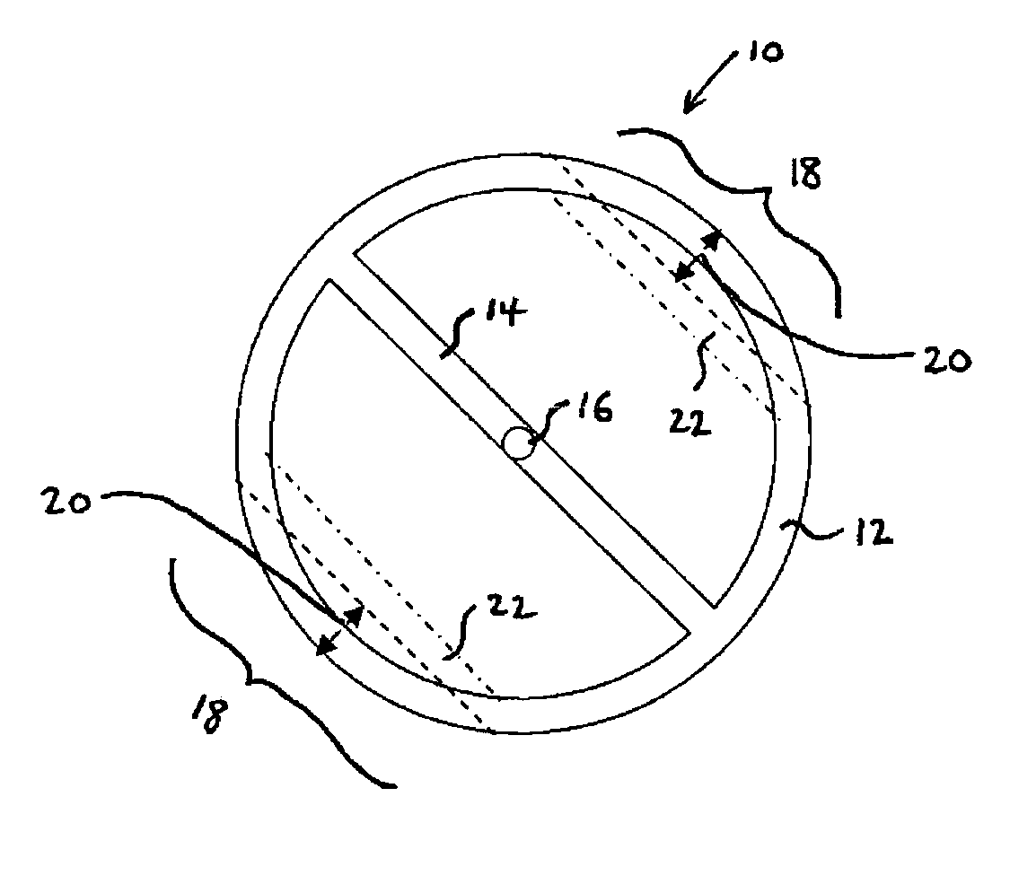
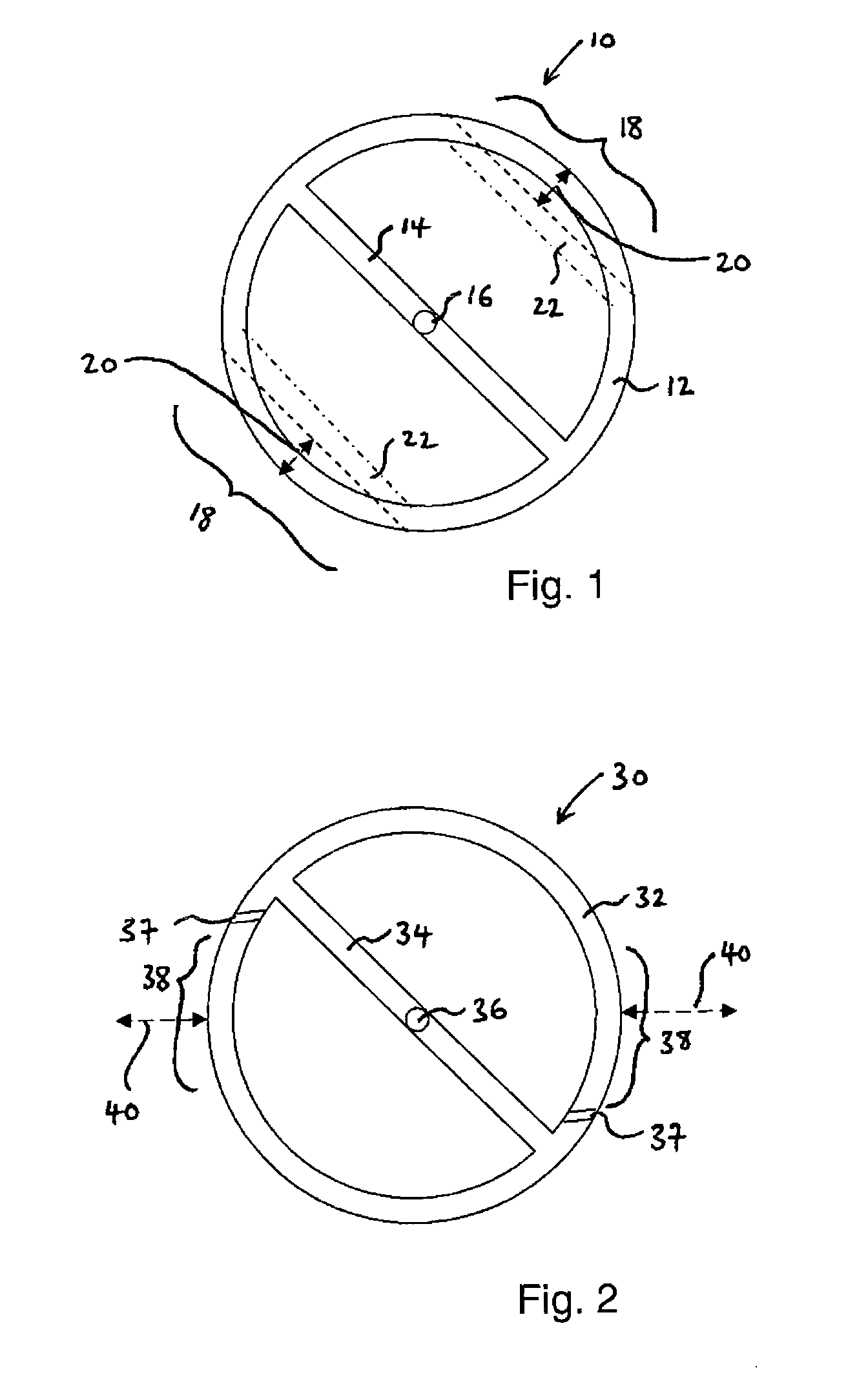
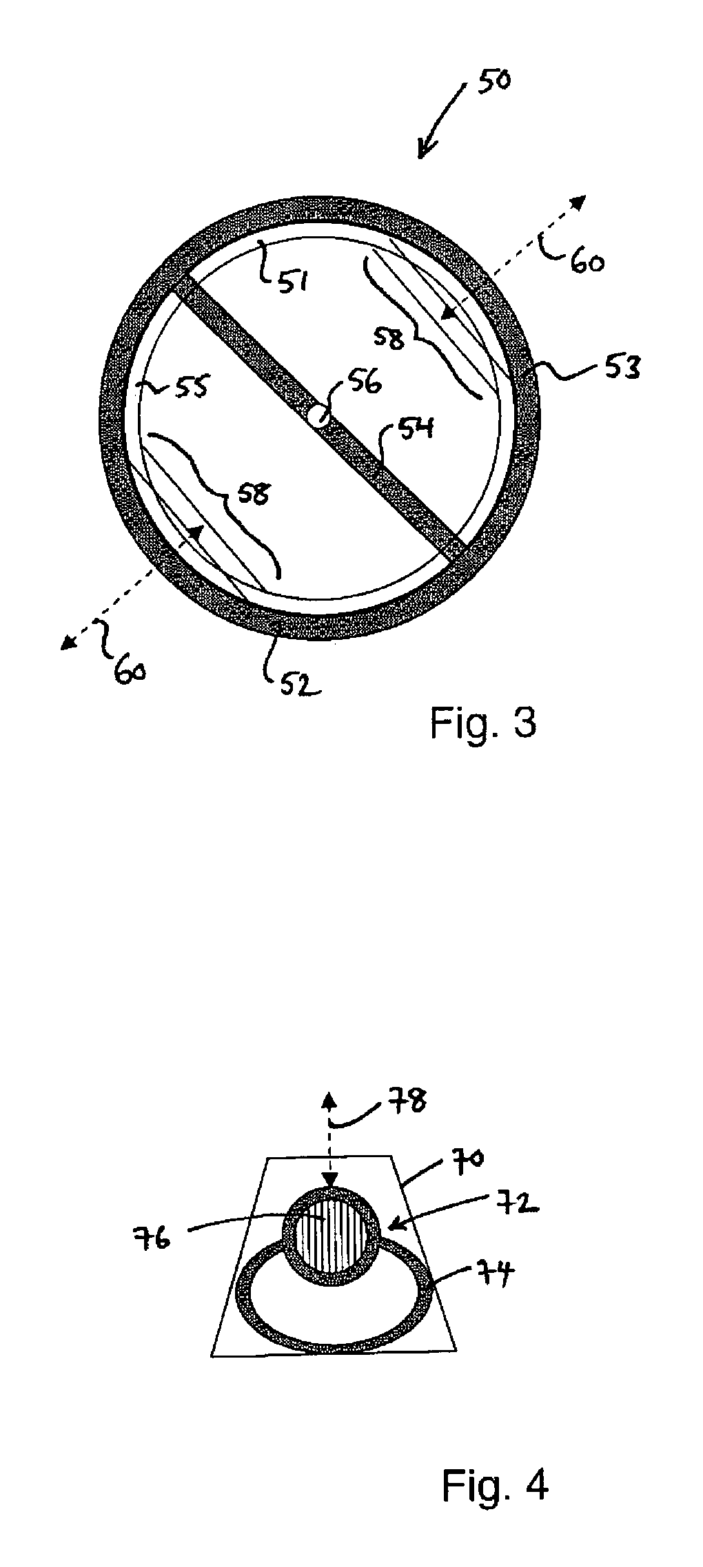
[0063]FIG. 1 is a plan view of a balance wheel 10 which incorporates a thermal compensation arrangement according to the first aspect of the invention. The balance wheel 10 has a generally circular rim 12 with a cross member 14 extending across a diameter thereof. At the centre of the cross member 14 there is an upstanding balance staff 16 to which a balance spring (not shown) is attached. In this embodiment, the rim includes two compensation portions 18 symmetrically arranged around the balance staff 16. The two compensation portions 18 are substantially identical to one another, so the symmetrical arrangement ensures that the balance wheel 10 remains in equipoise.

[0064]Each of the compensation portions 18 comprises shape memory material, which in this embodiment is a shape memory alloy of nickel-titanium. The compensation portions 18 are pre-programmed to exhibit a two-way shape memory effect whereby they move in the dire...


PUM


Abstract

A balance wheel having a thermally adjustable moment of inertia is described. In one aspect, the balance wheel includes radially movable compensation portions formed of shape memory material exhibiting a two-way memory effect. The radius of gyration of the balance wheel is therefore adjustable with temperature to compensate for thermoelastic effects in a balance spring attached to the balance wheel. In another aspect, a thermally stable balance wheel includes dynamically adjusting appendages whose expansion or contraction with temperature relative to the balance wheel cause change in its moment of inertia. The invention can compensate for both ‘normal’ and ‘abnormal’ thermoelastic spring behaviour.

Description

TECHNICAL FIELD[0001]The present invention relates to a balance wheel for a horological mechanism or other precision timing instrument. For example, the invention may be used in a mechanical oscillator for a precision watch.BACKGROUND TO THE INVENTION[0002]Conventionally, balance wheels for watches are made principally from metal. In a horological mechanism, a balance spring (e.g. hairspring) is arranged to oscillate the balance wheel, ideally with an isochronous period of oscillation.[0003]The period of oscillation T of a horological mechanism is given by the equationT=2π1G,1where I is the moment of inertia of the balance wheel and G is the torque of the balance spring. Further,I ∝ Mr2,   2where M is the mass of the balance wheel and r is its radius of gyration.[0004]External influences such as temperature change and magnetism can affect properties of the balance spring and balance wheel which can cause variations in the period of oscillation. For the horological mechanism to be ac...

Claims


Application Information

Patent Timeline
IPC IPC(8): G04B17/06G04B17/22
CPCG04B17/227G04B17/222
Inventor LEVINGSTON, GIDEON
Owner CARBONTIME
Why Eureka
Try Eureka