Distortion-compensated amplifier using predistortion technique

a technology of distortion compensation and amplifier, applied in the field of amplifier, can solve the problems of insufficient studies, inability to compensate the and further developments are required, and achieve the effect of high-precision distortion compensation and reduced distortion component influence due to the memory effect of the amplifier

Active Publication Date: 2006-08-29
KOKUSA ELECTRIC CO LTD
View PDF4 Cites 55 Cited by
  • Summary
  • Abstract
  • Description
  • Claims
  • Application Information

AI Technical Summary

Benefits of technology

[0044]The invention was made in view of the conventional issues. Accordingly, it is an object of the invention to provide a distortion-compensated amplifier by predistortion technique, which can reduce an influence by the memory effect.
[0049]Thus, with the simple construction, an influence of a distortion component due to the memory effect of the amplifier can be reduced.
[0058]Therefore, for example, with the simple construction, an influence of a distortion component by the AM—AM characteristic and AM-PM characteristic of an amplifier can be reduced. Furthermore, an influence of a distortion component due to the memory effect of an amplifier can be reduced. Thus, highly accurate distortion compensation can be implemented as a whole.
[0070]As described above, in order to compensate for distortion caused in an amplifier, which amplifies an input signal, by predistortion technique by using a distortion-compensated amplifier using predistortion technique according to the invention, a time difference of results of raising an input signal to even powers is used to compensate for a distortion component caused by the memory effect of the amplifier. Thus, with a simple construction, an influence of a distortion component due to the memory effect of the amplifier can be reduced. Therefore, highly accurate distortion compensation can be achieved.

Problems solved by technology

Furthermore, since nonlinear distortion may occur in the amplifier at some levels of input signals, the distortion may be compensated by a predistortion technique.
However, while distortion occurring in an amplifier ignoring the memory effect can be compensated by a conventional predistortion technique, influences due to the memory effect cannot be compensated, which is a problem.
While, in order to solve the problem, various studies have been made (refer to Non-patent Document 1, for example), studies are still not enough and further developments have been demanded.

Method used


Image

  • Distortion-compensated amplifier using predistortion technique
  • Distortion-compensated amplifier using predistortion technique
  • Distortion-compensated amplifier using predistortion technique

Examples


first example

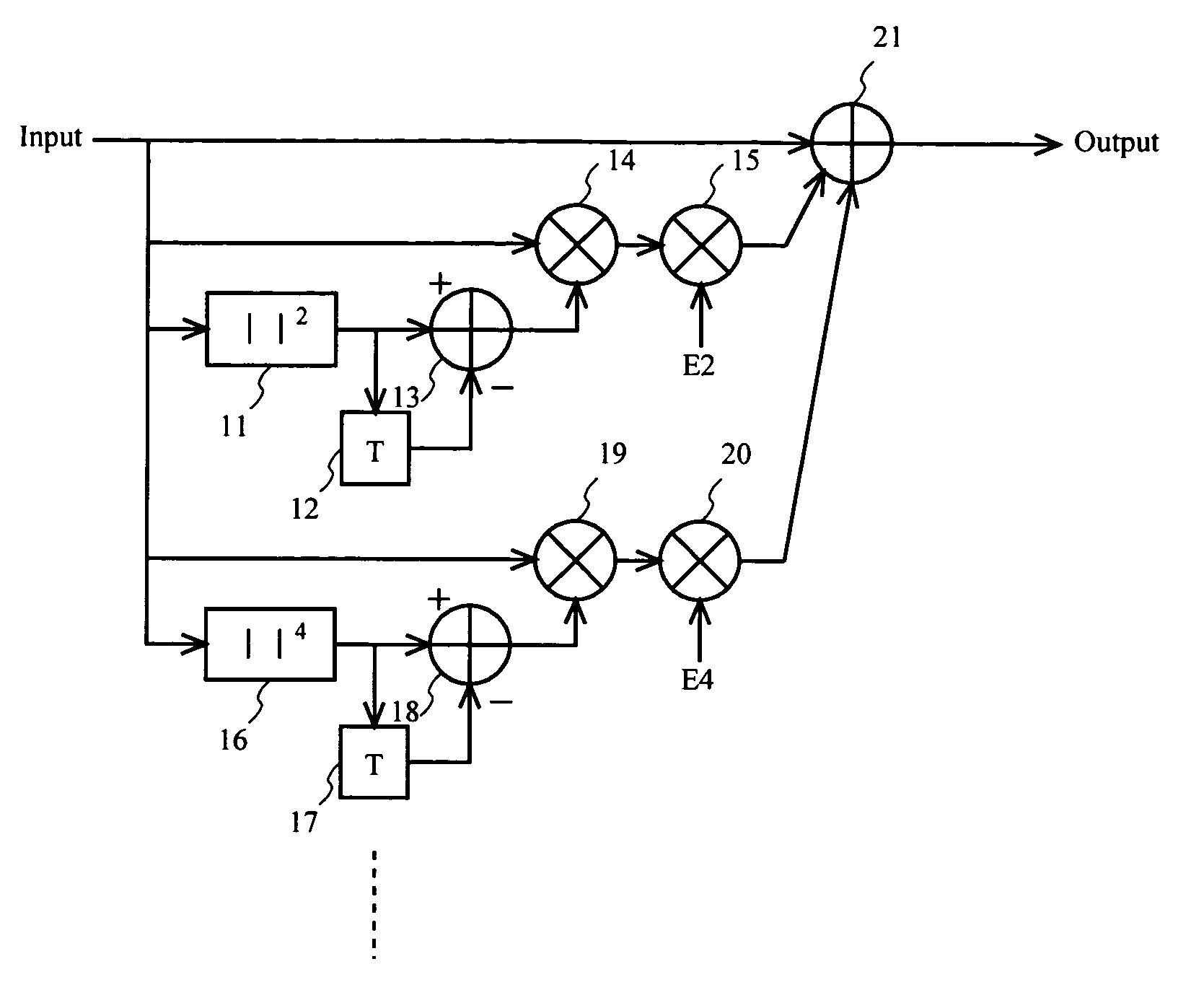
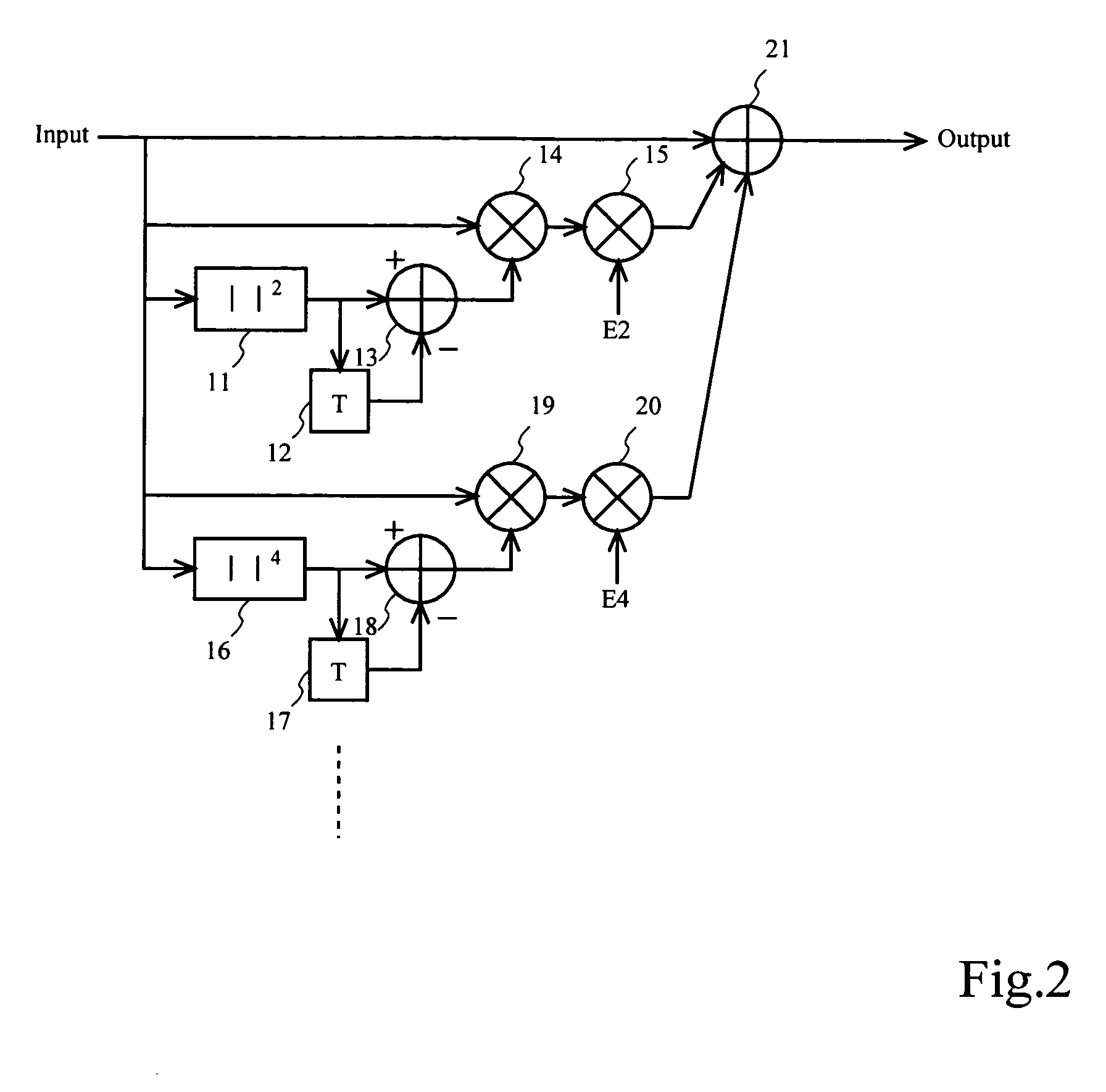
[0097]The memory effect predistorter 2 according to a first example of the invention will be described.

[0098]As shown in FIG. 2, the memory effect predistorter 2 of this example includes a square law detector 11, a delay circuit 12, a subtractor 13, and two (complex) multipliers 14 and 15, similarly, a fourth power law detector 16, a delay circuit 17, a subtractor 18 and two (complex) multipliers 19 and 20, and an adder 21.

[0099]An example of an operation of the memory effect predistorter 2 according to this example will be described.

[0100]Input signals are I, Q digital baseband signals with complex vectors. In this example, input signals are signals output from the predistorter 1.

[0101]The square law detector 11 detects a square value of predistorter input signals and generally calculates a value of (I2+Q2). The delay circuit 12 delays an output (detected value) from the square law detector 11 by T [sec]. The subtractor 13 subtracts the output of the square law detector 11 T [sec] ...

second example

[0115]A memory effect predistorter 2 according to a second example of the invention will be described.

[0116]As shown in FIG. 3, the memory effect predistorter 2 according to this example includes a square-law detector 31, a delay circuit 32, a subtractor 33, a look-up table (LUT) 34, and a (complex) multiplier 35. Here, operations of the square law detector 31, delay circuit 32 and subtractor 33 are the same as those of the square law detector 11, delay circuit 12 and subtractor 13 in FIG. 2, for example.

[0117]The LUT 34 stores a table for memory-effect compensation, which is automatically converged by a control portion 4. For the LUT 34, an output from the subtractor 33 is used as a table reference argument.

[0118]The multiplier 35 multiplies a complex vector for distortion compensation stored in the LUT 34 by an input signal, and the multiplication result is handled as a signal output to the amplifying section 3.

[0119]When a signal output from the memory effect predistorter 2 in th...

third example

[0122]A memory effect predistorter 2, which is an RF predistorter according to a third example of the invention, will be described.

[0123]As shown in FIG. 4A, the memory effect predistorter 2 in this example includes a square law detector 41 having a square circuit, a delay circuit 42 having a delay element, a subtractor 43 having hardware such as an operational amplifier, an analog-to-digital (A / D) converter 49a for performing A / D conversion, a look-up table (LUT) 44, two digital-to-analog (D / A) converters 45 and 46, a voltage adjustable attenuator 47, and a voltage adjustable phase shifter 48. Here, operations of the square law detector 41, the delay circuit 42, the subtractor 43 and the LUT 44 are the same as those of the square law detector 31, the delay circuit 32, the subtractor 33 and the LUT 34 shown in FIG. 3. Alternatively, in another construction shown in FIG. 4B, instead of the A / D converter 49a shown in FIG. 4A, an A / D converter 49b is provided next to the square law det...


PUM


Abstract

A memory effect distortion component compensating unit compensates for a distortion component caused by a memory effect of an amplifier by using a time difference of results from raising an input signal to even power. For example, the amplifier may include a memory effect distortion component compensating unit having an even power raising unit for raising an input signal to even power, an even power raising result delaying unit for delaying a signal of a result of even power raising, an even power raising result time difference detecting unit for detecting a difference between a signal of an even power raising result and a delayed signal, an input signal multiplying unit for multiplying a signal of a detection result by an input signal, a distortion compensation coefficient multiplying unit for multiplying a signal of a multiplication result by a distortion compensation coefficient, and a distortion compensation coefficient multiplication result adding unit for adding an input signal and a signal of a multiplication result.

Description

BACKGROUND OF THE INVENTION[0001]1. Field of the Invention[0002]The present invention relates to an amplifier having a function for compensating for distortion by predistortion technique (which will be called distortion-compensated amplifier using predistortion technique below) and, in particular, to a technology for reducing an influence due to the memory effect.[0003]The technical background of the invention will be described below. However, all of those described below may not be conventional technologies.[0004]For example, in a base station apparatus of a mobile communication system adopting Wide-band Code Division Multiple Access (W-CDMA) as a mobile communication technique, radio signals must be transmitted to the physically remote base station apparatus. Therefore, signals such as multi-carriers must be largely amplified by an amplifier such as a power amplifier (PA).[0005]However, since an amplifier is an analog device, the input / output characteristic is a nonlinear function...

Claims


Application Information

Patent Timeline
Patent Type & Authority Patents(United States)
IPC IPC(8): H03F1/26H03F1/32
CPCH03F1/3258H03F2201/3224
Inventor HONGO, NAOKIMIYATANI, TETSUHIKOAKAIWA, YOSHIHIKO
Owner KOKUSA ELECTRIC CO LTD
Why Eureka
Try Eureka