
Method and system for multi-energy computer tomographic cuttings analysis

a multi-energy, computer-based technology, applied in material analysis using wave/particle radiation, instruments, nuclear engineering, etc., can solve the problems of sample size versus formation or facies size, difficult physical lab experiments, and time-consuming, etc., to improve processing and analysis of digital images.

Active Publication Date: 2017-08-29
HALLIBURTON ENERGY SERVICES INC
View PDF39 Cites 6 Cited by
  • Summary
  • Abstract
  • Description
  • Claims
  • Application Information

AI Technical Summary

Benefits of technology

Enables rapid and accurate estimation of rock properties and facies characterization, facilitating real-time decision-making during drilling and improving the accuracy of rock property estimation across large formations.

Problems solved by technology

Laboratory analysis of rock samples can be difficult and time consuming.
Physical lab experiments are difficult to perform due to the size and shape of cuttings.
When rock properties are estimated using digital rock physics, the problem of sample size versus formation or facies size is even more extreme.
However, it is very time consuming and expensive to digitally scan very large samples to estimate rock properties.
The difference in scale between the sample (core) and the pores contained in the sample can complicate pore analysis thereof.
However, scanning the entire sample at a resolution high enough to identify all of the pores is not practical due to the time and expense required to do a complete scan.
Underground facies typically do not follow straight lines and as such, significant errors in estimating location of facies can occur.
It may not be practical to extract horizontal cores from a well bore and vertical cores may provide only limited data.
Core analysis is not practical in real time or near-real time.
Cores must be extracted and shipped to a laboratory for analysis and this can require many days or weeks to complete.

Method used


Image

  • Method and system for multi-energy computer tomographic cuttings analysis
  • Method and system for multi-energy computer tomographic cuttings analysis
  • Method and system for multi-energy computer tomographic cuttings analysis

Examples


Embodiment Construction

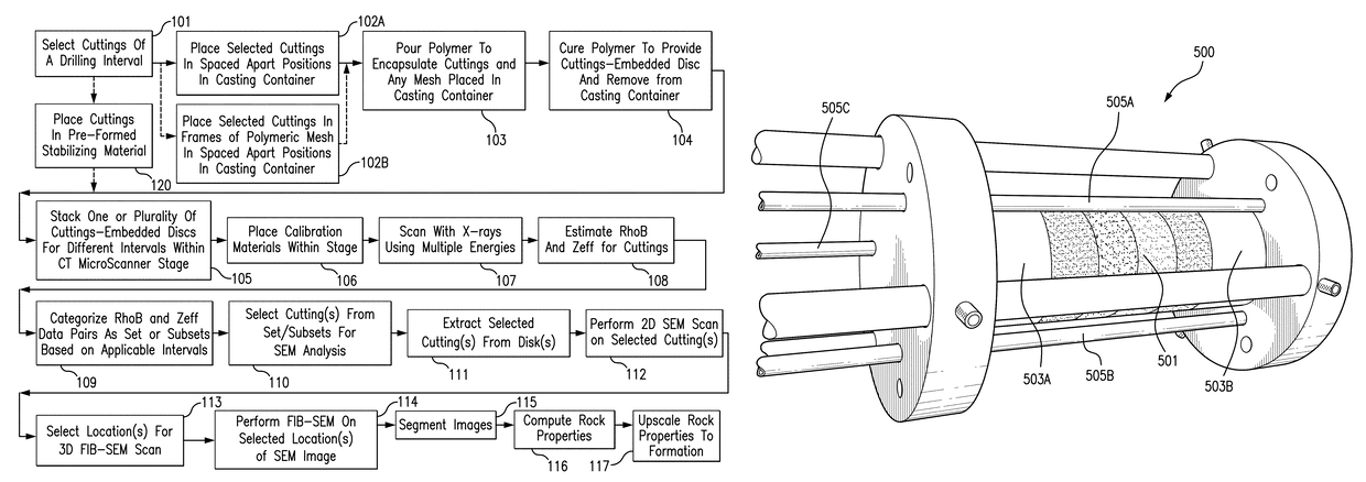
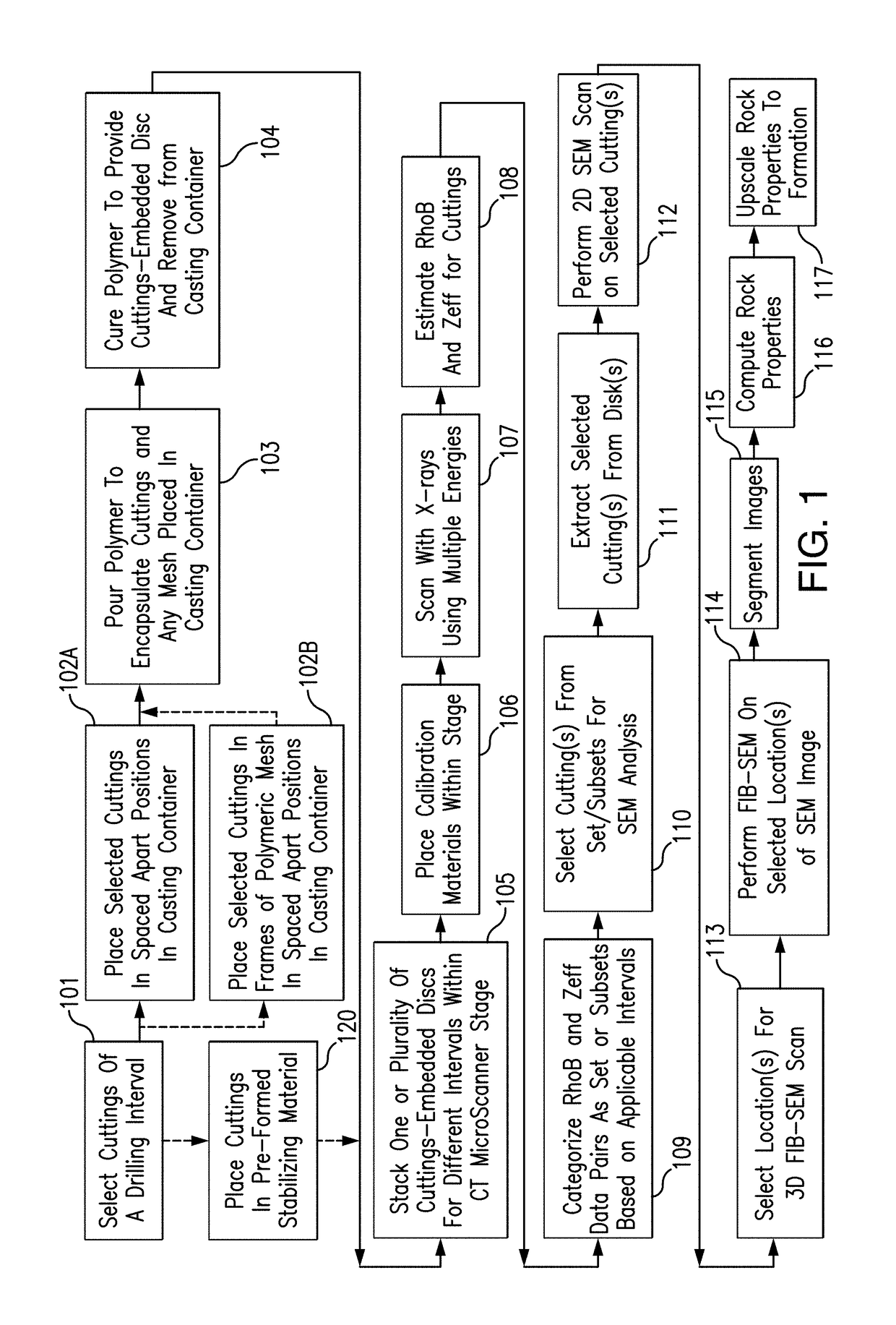
[0049]The present invention relates in part to a method which allows organization of mass quantities of rock fragments such as drill cuttings obtained from one or more intervals of a well to more accurately categorize the cuttings to assist in selections of cuttings thereof for more detailed digital rock analysis. The method of the present invention makes it possible, for example, to screen through a large number of samples of rock fragments obtained from a single well interval or multiple well intervals to identify a sample or samples thereof for each interval that would be a better candidate(s) for use in more detailed analyses used to obtain estimates of rock properties of the formation or facies from which the rock fragments are obtained. For example, rock fragments can be selected using a method of the present invention which can better typify or otherwise have more relevant features or content for use in more detailed imaging systems, such as SEM, FIB-SEM or high resolution CT...


PUM

PropertyMeasurementUnit
diameteraaaaaaaaaa
diameteraaaaaaaaaa
pore sizeaaaaaaaaaa

Abstract

A method and a system are provided to prepare a plurality of cuttings or other rock fragments or other porous media, such as cuttings from a drilling interval or multiple intervals, for computer tomographic scanning at the same time. A method and system also are provided to allow organization of mass quantities of cuttings or other rock fragments obtained from intervals of a well to more accurately categorize the cuttings to assist selections thereof for more detailed digital rock analysis, such as using SEM and FIB-SEM systems, are provided. A method and system also are provided to allow characterization of facies occurrence frequency of a depth interval using drill cuttings or other rock fragments. Computerized systems, computer readable media, and programs for performing the methods are also provided.

Description

[0001]This application claims the benefit under 35 U.S.C. §119(e) of prior U.S. Provisional Patent Application Nos. 61 / 646,045, filed May 11, 2012, and 61 / 652,567, filed May 29, 2012, which are incorporated in their entireties by reference herein.BACKGROUND OF THE INVENTION[0002]This invention relates to the field of digital rock physics and, more particularly, to methods to select drill cuttings or other rock fragments for further analysis and to characterize facies occurrence frequency of a depth interval using drill cuttings or other rock fragments.[0003]Estimating rock properties, such as porosity, total organic content, permeability, and composition, and so forth, has substantial significance, such as for characterizing the economic value of reservoir rock formations. Laboratory analysis of rock samples can be difficult and time consuming. Physical lab experiments are difficult to perform due to the size and shape of cuttings. Devices for generating digital images of rock sampl...

Claims


Application Information

Patent Timeline
Patent Type & Authority Patents(United States)
IPC IPC(8): G01N23/04G01N23/087G01N23/10G01N1/36
CPCG01N23/046G01N23/087G01N1/36G01N23/10G01N2223/419G01N2223/616G01N2223/649G01N23/083
Inventor GRADER, AVRAMIDERZHI, NAUMGUZMAN, BRYAN
Owner HALLIBURTON ENERGY SERVICES INC
Learn More