System and method for providing improved event reading and data processing capabilities in flow cytometer

a flow cytometer and event technology, applied in the field of system and method for improving the event reading, data processing and system configuration can solve the problems of time delay, system failure to capture the entire image of the event, and existing system drawbacks, so as to improve the event reading and data processing capabilities of the flow cytometer and achieve efficient system configuration assessment capabilities.

Inactive Publication Date: 2005-02-24
YOUNT DWAYNE +5
View PDF0 Cites 15 Cited by
  • Summary
  • Abstract
  • Description
  • Claims
  • Application Information

AI Technical Summary

Benefits of technology

[0018] An object of the present invention is to provide a system and method for use with a flow cytometer to improve event reading and data processing capabilities of the flow cytometer, while also providing efficient system configuration assessment capabilities.
[0019] Another object of the present invention is to provide a system and method that enables a flow cytometer to capture and sample an entire waveform representative of an event being read, and which provides improved processing and analysis of the sampled data in a real-time or near real-time basis.
[0020] A further object of the present invention is to provide a system and method that is capable of indicating the configuration of a flow cytometer to an operator in an efficient and effective manner.

Problems solved by technology

Hence, a time delay exists from when the cell is at the interrogation point until the cell reaches the actual break-off point of the droplet.
Although the flow cytometers described above can be suitable for reading events as intended, these existing systems do suffer from certain drawbacks.
These existing systems also do not capture the entire image of the event.
However, these techniques do not enable the existing systems to sample individual regions of the cell or particle of interest, nor are they capable of being performed on a real-time or near real-time basis.
Furthermore, these systems are typically incapable of comparing data from multiple events effectively and in a real time or near real-time manner.
In addition, these types of existing systems do not provide a mechanism that indicates the configuration of the system to the operator effectively.
However, if an incorrect filter is placed in front of a particular detector, the detector will detect the incorrect light (e.g., green light instead of blue light).
The system will therefore give erroneous results.
However, the operator of the system will have difficulty determining which filters are arranged incorrectly, and in the worst case, the error may go unnoticed.

Method used


Image

  • System and method for providing improved event reading and data processing capabilities in flow cytometer
  • System and method for providing improved event reading and data processing capabilities in flow cytometer
  • System and method for providing improved event reading and data processing capabilities in flow cytometer

Examples


Embodiment Construction

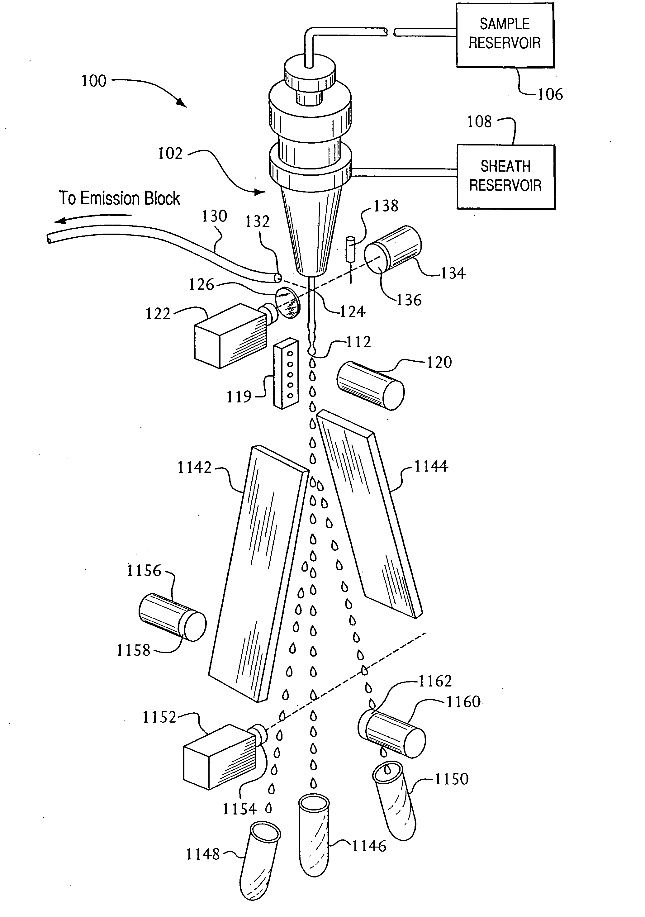
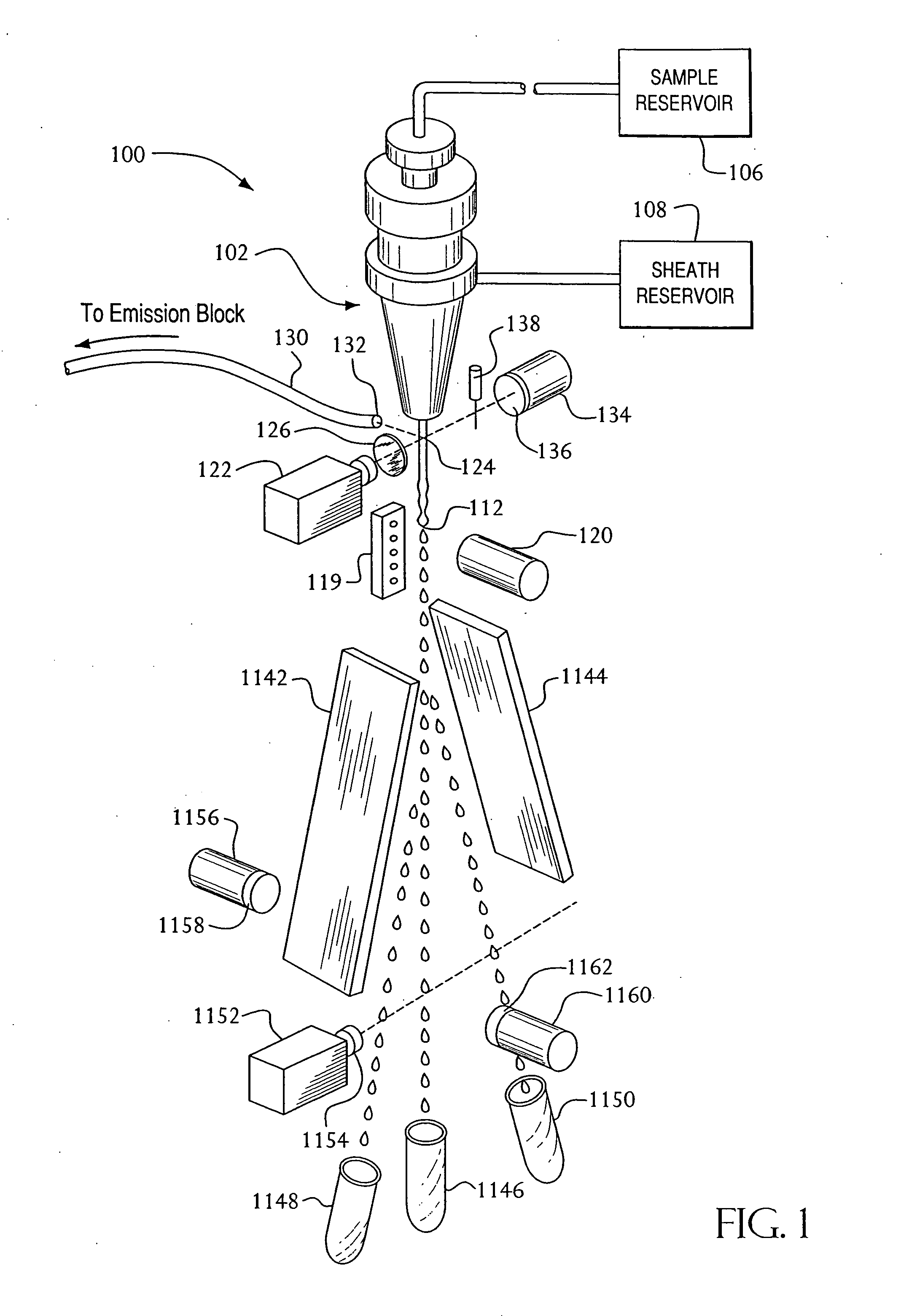
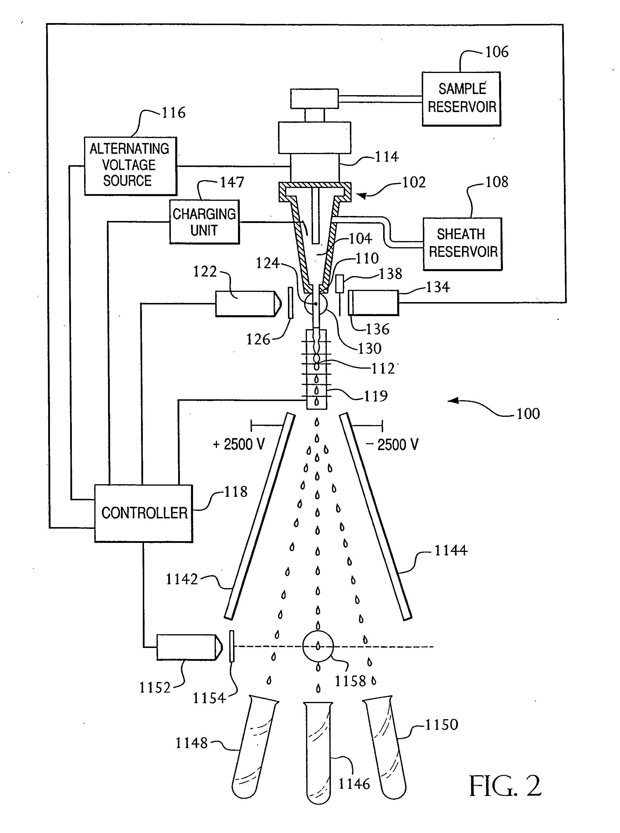
[0042] A flow cytometer 100 employing an embodiment of the present invention is illustrated in FIGS. 1 and 2. As discussed in the background section above, the flow cytometer 100 includes a nozzle 102 having a flow cell 104 therein. The flow cytometer further includes a sample reservoir 106 for receiving a fluid sample,. such as a blood sample, and a sheath reservoir 108 containing a sheath fluid. The flow cytometer transports the cells in the fluid sample in the cell stream to the flow cell 104, while also directing the sheath fluid to the flow cell 104.

[0043] Within the flow cell 104, the sheath fluid surrounds the cell stream, and the combined sheath fluid and cell stream exits the flow cell 104 via an opening 110 as a sample stream. The opening 110 can have a diameter of, for example, 50 μm, 70 μm, 100 μm, or any other suitable diameter. As illustrated, due to characteristics of the sheath fluid, such as surface tension and the like, the sample stream remains intact until break...


PUM

PropertyMeasurementUnit
diameteraaaaaaaaaa
diameteraaaaaaaaaa
diameteraaaaaaaaaa

Abstract

A system and method for use with a flow cytometer to improve event reading and data processing capabilities of the flow cytometer, while also providing efficient system configuration assessment capabilities. The system and method enables the flow cytometer to capture and sample an entire waveform representative of an event being read, and provides improved processing and analysis of the sampled data in a real time or near real-time basis. The system and method further enable the flow cytometer to assess its configuration and provide assessment results to an operator in an efficient and effective manner.

Description

[0001] The present invention claims benefit under 35 U.S.C. § 119(e) of a U.S. Provisional Patent Application of Dwayne Yount et al. entitled “Hardware and Electronics Architecture for a Flow Cytometer”, Ser. No. 60 / 203,515, filed May 11, 2000, of a U.S. Provisional Patent Application of Michael Lock et al. entitled “Cluster Finder Algorithm for Flow Cytometer”, Ser. No. 60 / 203,590, filed May 11, 2000, of a U.S. Provisional Patent Application of Michael Goldberg et al. entitled “User Interface and Network Architecture for Flow Cytometer”, Ser. No. 60 / 203,585, filed May 11, 2000, and of a U.S. Provisional Patent Application of John Cardott et al. entitled “Digital Flow Cytometer”, Ser. No. 60 / 203,577, filed May 11, 2000, the entire contents of each of said provisional patent applications being incorporated herein by reference. CROSS-REFERENCE TO RELATED APPLICATIONS [0002] Related subject matter is disclosed in a copending U.S. patent application of Pierce 0. Norton entitled “Apparat...

Claims


Application Information

Patent Timeline
Patent Type & Authority Applications(United States)
IPC IPC(8): G01N15/10G01N15/14G06K9/62
CPCG01N15/1459G06K9/6218G01N2015/1477G01N2015/1006G06F18/23
Inventor YOUNT, DWAYNEBROWN, SCOTTPAYAVALA, SREEDHARSTOKDIJK, WILLEMHOPKINS, PERRYHELMS, STEVEN
Owner YOUNT DWAYNE
Why Eureka
Try Eureka