Light-weight, soft wing-sail for wind-propelled vehicle

a technology of soft wings and wind-propelled vehicles, which is applied in the direction of propulsive elements, floating buildings, vessel construction, etc., and can solve the problems of less safe at sea, negative effects on boat stability and performance,

Inactive Publication Date: 2009-10-20
GONEN ILAN
View PDF4 Cites 8 Cited by
  • Summary
  • Abstract
  • Description
  • Claims
  • Application Information

AI Technical Summary

Benefits of technology

[0005]An object of the present invention is to provide a light-weight and simple construction of soft wing-sail, for wind-propelled vehicle, having a number of advantages in the above respects, as will be described more particularly below.
[0008]In addition, each of the sliders includes a batten receptacle for receiving the batten of the respective sail panel. In addition, the tracks grooves receiving sliders secured to each of the sail panels, thereby permitting hoisting and reefing the sail panels either independently or together.
[0009]According to further features in the described preferred embodiment, the sliders are secured to both ends of the front sail panel and to each of the front ends of the side sail panels. Each of the sliders includes a batten receptacle for receiving the batten of the respective sail panel. In addition, each of the tracks includes fore and aft grooves for independently receiving its sliders, thereby permitting hoisting and reefing the sail panels independently or together.
[0014]According to still further features in the described preferred embodiment, a reefing block coupling a reefing line to reefing points on the trailing edges of said side sail panels permitting reefing said side sail panels together and under even tension such as to enable the windward side of the trailing edge to slide rearwardly relative to the boom, and the leeward side of the trailing edge to slide forwardly relative to the boom, when the wing is reefed and the angle between the mast and the boom is changed in order to trim the airfoil shape. In addition, the outer ends of the bottom spreader are secured to the opposite sides of the lower end of the mast such that the mast, the spreaders and the tracks provide a stiff and light-weight structure for supporting the mast from whipping.
[0015]As will be described more particularly below, such a light-weight and simple construction permits the soft wing-sail to be hoisted, reefed, and lowered, either as one wing-sail unit, or each of the sail panels independently. The higher efficiency capability of such a light-weight soft wing-sail enables the vehicle to attain higher speeds of travel and point higher up wind, and at the same time, to reduce the size of the sails and rigging and to reduce the weight of the vehicle. Also, it enables a safe and easy operation of a vehicle driven by the wind.

Problems solved by technology

However, the main disadvantages of the structure of soft wing-sails proposed were cumbersome and / or heavy structure that is hard to use and to fix damages at sea and, has negative effects on boats stability and performance.
Also, complicated structure with many moving parts tends to jam and stick and therefore is less safe at sea.

Method used


Image

  • Light-weight, soft wing-sail for wind-propelled vehicle
  • Light-weight, soft wing-sail for wind-propelled vehicle
  • Light-weight, soft wing-sail for wind-propelled vehicle

Examples


Embodiment Construction

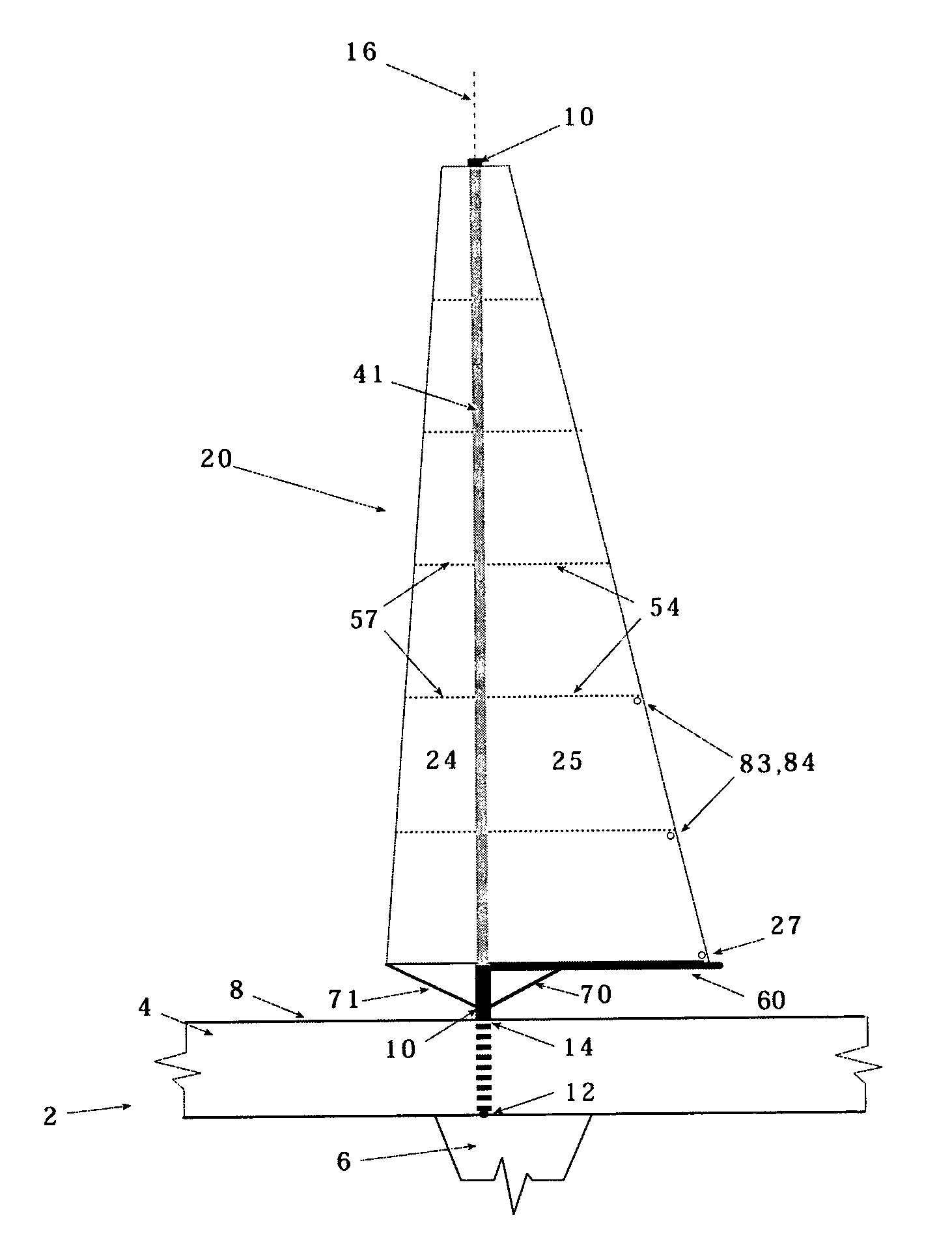
[0027]With reference to FIG. 1, there is illustrated a wind-propelled water vehicle, generally designated 2, including a hull 4, a keel 6, and a deck 8. Also illustrated in FIG. 1 is a free-standing and rotatable mast, generally designated 10, vertically mounted for rotation by means of a ball 12 at the level of keel 6, and a roller bearing 14 at the level of the deck 8, such as to permit rotation of the mast about its vertical axis 16.

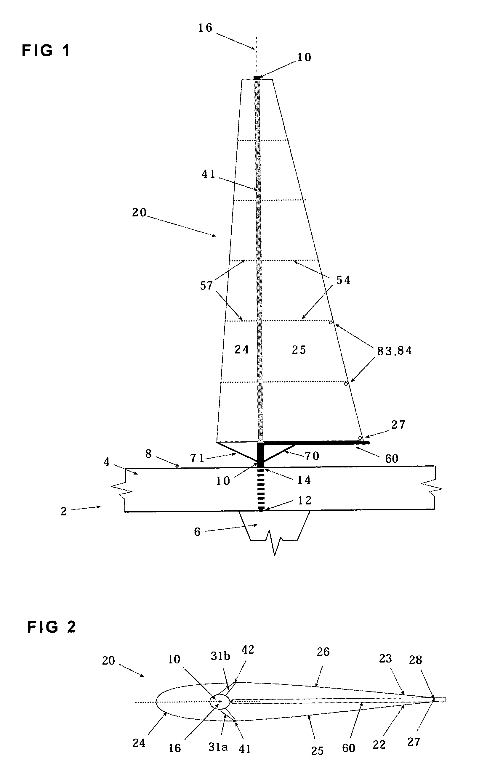
[0028]Vertical mast 10 carries a light-weight, soft wing-sail, generally designated 20, for propelling the vehicle. As shown particularly in FIG. 2, wing-sail 20 is supported on mast 10 such as to assume a selected airfoil shape having a leading edge defined by a U-shaped panel 24 fore of the mast, and a trailing edge aft of the mast defined by two spaced side panels 25, 26. As shown particularly in FIGS. 1, 2 and 6, the lower aft side of the trailing edge side panels 25, 26 includes clews 27, 28.

[0029]The selected airfoil shape of the wing-sail 20 is...


PUM


Abstract

A light-weight soft wing-sail for a wind-propelled vehicle includes a free standing rotating mast to be mounted in a vertical position on the vehicle and, three fully battened sail panels that together define the skin of the wing sail. Spreaders extend transversely of the mast and impart to them a selected airfoil shape having a leading edge fore of the mast and a trailing edge aft of the mast. Two vertical tracks secured to both sides of the mast top and to the outer ends of each spreader. Sliders are secured to the sail panels and are slidable in the tracks, such as to permit hoisting and reefing each of the sail panels independently along the tracks. A boom is pivotally coupled to the mast and a ram is secured on one side to the lower spreader and on the other side to the boom such that the leading edge and the trailing edge define one wing-sail unit and trims the airfoil shape. An outhaul line pulls the clews of both trailing edges together through a block to evenly tension rearwardly the clews of the trailing edge and also to permit each of the clews to independently slide along the boom when the airfoil shape is changed.

Description

FIELD AND BACKGROUND OF THE INVENTION[0001]The present invention relates to wind-propelled vehicles, and particularly to light-weight soft wing-sails for propelling such vehicles. The invention is especially useful in water vehicles, and is therefore described below with respect to such application, but it will be appreciated that the invention could also be used in other applications, such as for propelling vehicles over land or ice.[0002]In recent years, a number of soft wing-sails have been proposed in order to better exploit the wind forces for propelling the vehicle. Examples of various constructions of soft wing-sails heretofore proposed are described in Fuller U.S. Pat. No. 4,685,410; Magrini U.S. Pat. No. 5,271,349; Milidragivic U.S. Pat. No. 5,868,092; Gonen U.S. Pat. No. 6,863,008; and in U.K. Patent Spencer 2,008,514.[0003]However, the main disadvantages of the structure of soft wing-sails proposed were cumbersome and / or heavy structure that is hard to use and to fix dama...

Claims


Application Information

Patent Timeline
Patent Type & Authority Patents(United States)
IPC IPC(8): B63B35/00
CPCB63H9/08B63H9/0607B63H9/061
Inventor GONEN, ILAN
Owner GONEN ILAN
Why Eureka
Try Eureka